Manufacture of carbon composites by hot pressing

a carbon composite and hot pressing technology, applied in friction lining, electric/magnetic/electromagnetic heating, transportation and packaging, etc., can solve the problems of increasing weight, and increasing the cost of composites. , to achieve the effect of improving oxidation stability, improving machinability, and high friction coefficien

Inactive Publication Date: 2005-04-12
GRAFTECH INT HLDG INC
View PDF45 Cites 41 Cited by
  • Summary
  • Abstract
  • Description
  • Claims
  • Application Information

AI Technical Summary

Benefits of technology

An additional advantage of the invention is that the carbon / carbon composite which includes the friction additive has a higher coefficient of friction than the carbon / carbon composite without the additive. A further advantage is that the invention may be used to incorporate the additive substantially uniformly throughout the carbon / carbon composite.
is that the carbon / carbon composite which includes the friction additive has a higher coefficient of friction than the carbon / carbon composite without the additive. A further advantage is that the invention may be used to incorporate the additive substantially uniformly throughout the carbon / carbon composite.
A further advantage of the inventive carbon / carbon composite which includes the friction additive is that inventive composite has improved oxidation stability as compared to a carbon / carbon composite without such friction additive.
Furthermore, the inventive carbon / carbon composite impregnated with the treat component has exhibited the advantage of improved machinability as compared to composites formed by other methods. Also, the composite has exhibited improved fade / friction properties as well as improved erosion resistance.
Another advantage of the invention is that a carbon composite having a carbonized matrix comprising the treat component may be used as a brake pad on a metal surface of a braking element, such as a rotor or brake drum.

Problems solved by technology

This carbonization step is carried out in an inert atmosphere and often takes several days to complete.
The lengthy heating and infiltration times render such composites expensive and impractical for many applications.
Accordingly, sintered metal articles are commonly used for thermal applications, despite their greater weight and often poorer thermal stability and friction properties.

Method used


Image

  • Manufacture of carbon composites by hot pressing
  • Manufacture of carbon composites by hot pressing
  • Manufacture of carbon composites by hot pressing

Examples


example 1

Carbon / Carbon Composite Made by Dry Mixing of Precursor Materials

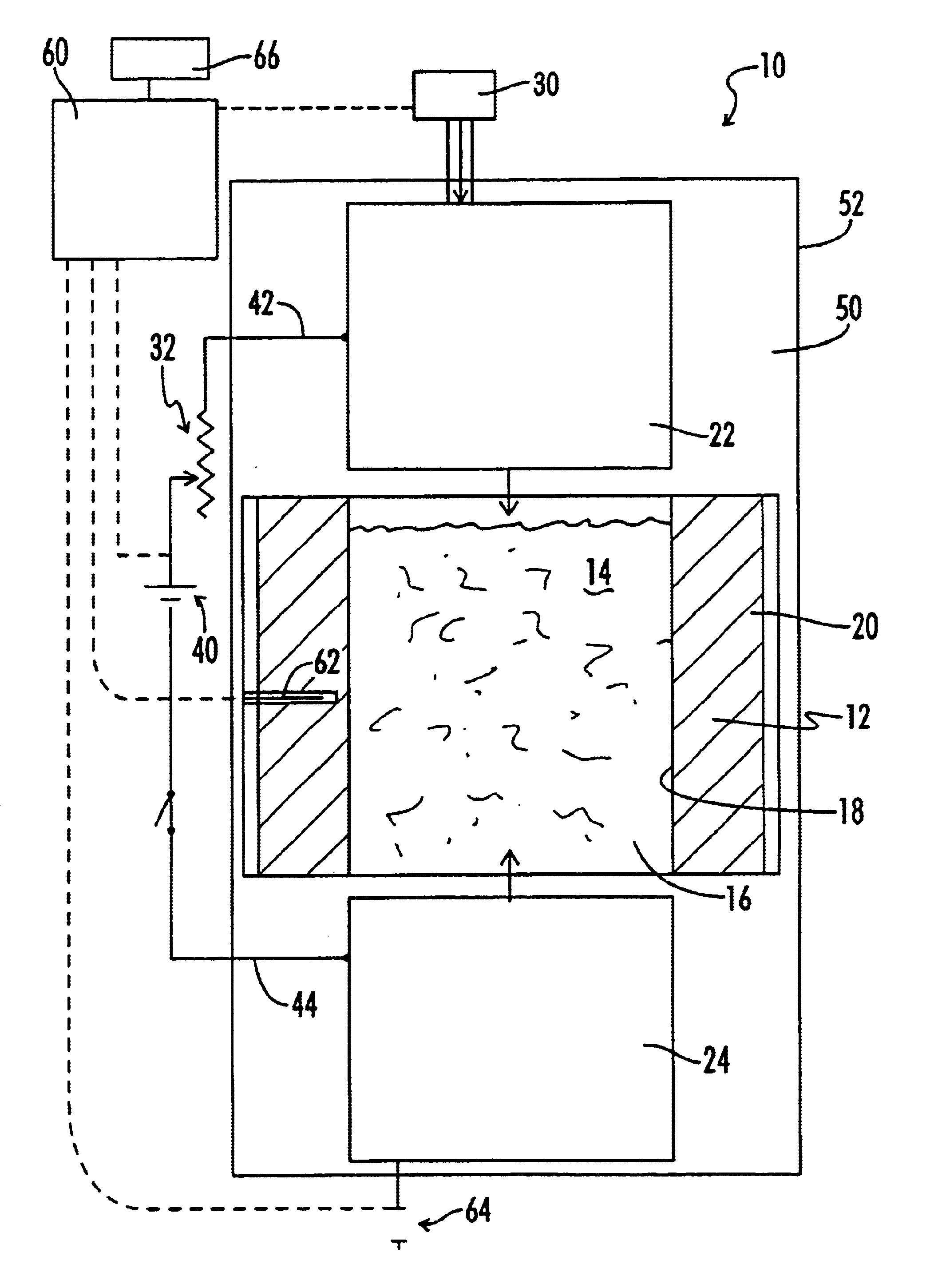
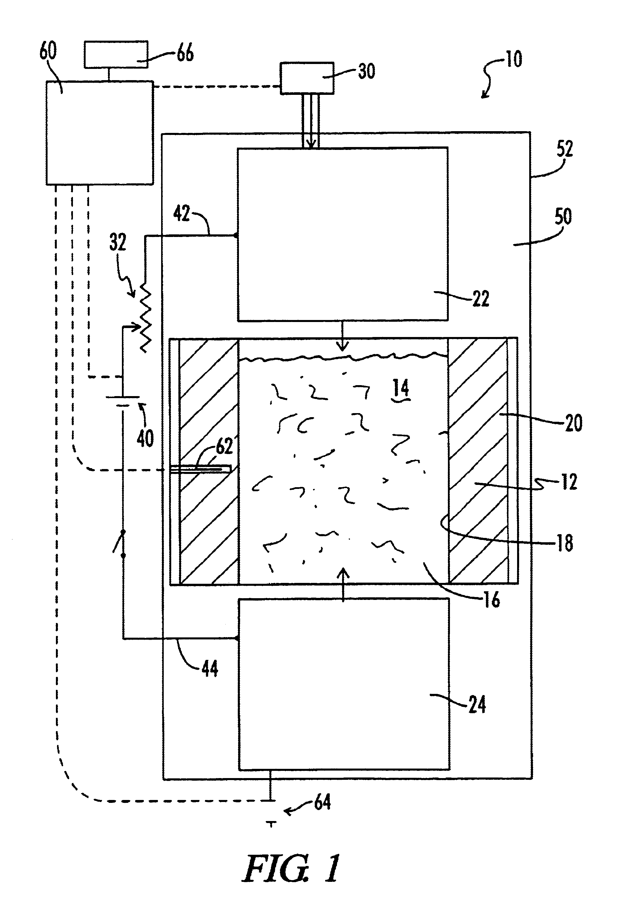
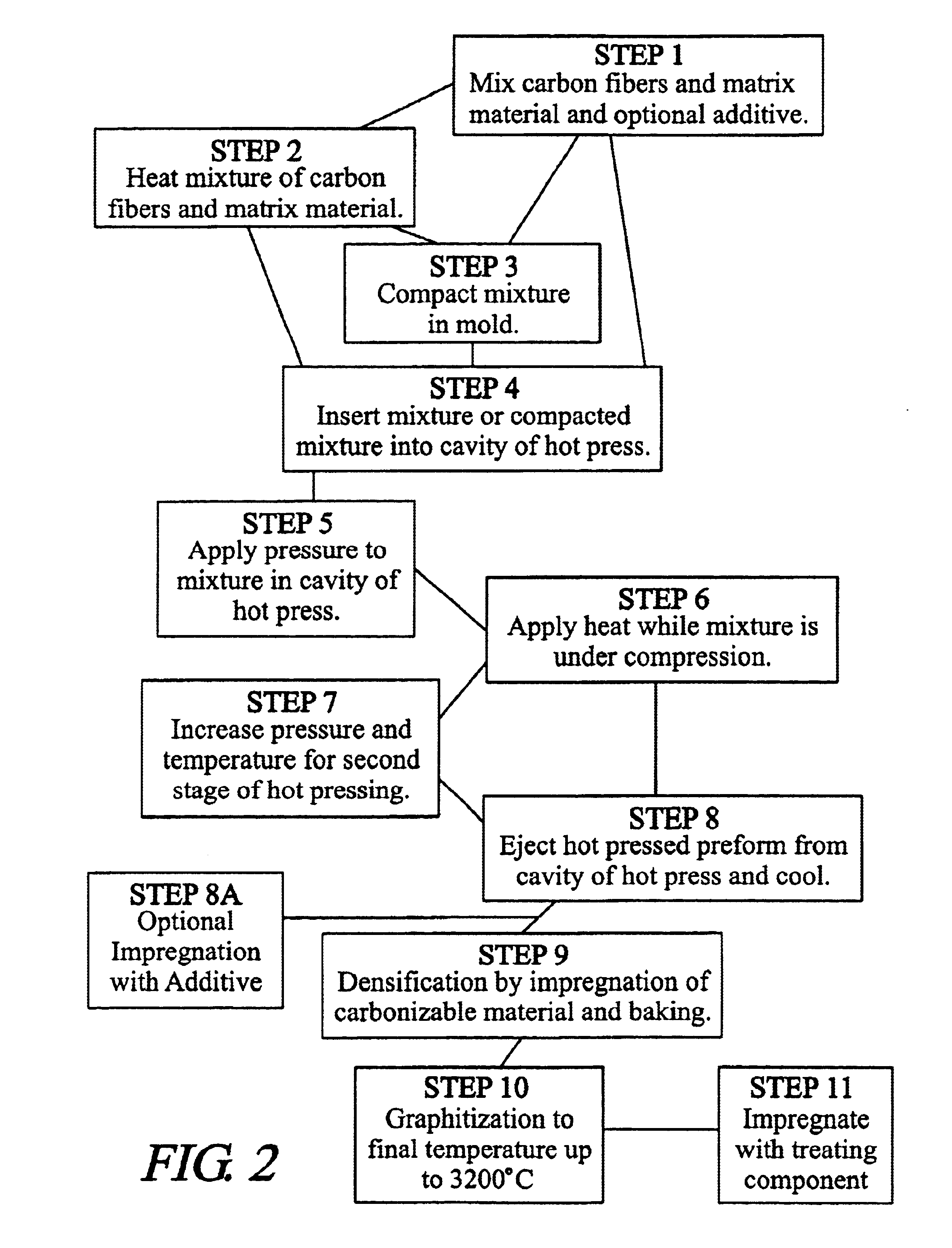
Mesophase pitch-based carbon fibers and a matrix material of milled pitch with 170° C. Mettler softening point (“SP”) (ASTM D 3104) and 70% coking yield were dry mixed at ambient temperature in a Sigma-type blender or similar type of mixer for about 5-15 minutes. The ratio of fibers to pitch matrix material was from 50-80 wt % fiber: 20-50 wt % pitch. The mixture was collected and charged into a mold box cavity (dimensions approximately 23×20 cm) of a hot press, as illustrated in FIG. 1. A pressure of up to about 140 kg / cm2 was applied to the mixture in the press. After pressing to compact the mixture, an electric current of about 1000-2000 amps (a power input of about 30-60 kW / kg) was passed through the mixture. The mix was held under the temperature and pressure conditions for about 5-10 minutes. The temperature of the mixture reached 800-900° C. This hot pressing process carbonizes and densifies the fiber / matrix mix...

example 2

Carbon / Carbon Composite Made by Hot Mixing of Precursor Materials

Various batches of mesophase pitch-based carbon fibers and a matrix material of milled pitch from Example 1 were hot mixed at a temperature of about 200° C. in a Sigma-type blender or similar type of mixer for about 30-45 minutes. The ratio of fibers to pitch matrix material was varied from about 50-80 wt % fiber: 20-50 wt % pitch. During the hot mixing, the matrix material coated the fibers uniformly. The mixture was collected and charged into a mold box cavity of a hot press, and heated and pressed as described for Example 1. Alternatively,.the mixture was compacted in a separate mold to a density of between about 0.5 and 1.0 g / cm3 prior to hot pressing.

A pressure of up to 140 kg / cm2 was applied to the mixture in the hot press. After pressing to compact the mixture, an electric current as high as 1500-2000 A (a power input of about 45-60 kW / kg) was passed through the mixture. The mix was held under the temperature an...

example 3

Silicon Carbide Carbon / Carbon Composite Made by Hot Mixing of Precursor Materials

Direct Addition of Solid SiC.

Blends of silicon carbide powder with an average particle size of about 10-20 microns from Alfa Aesar Company were blended with mixtures of chopped mesophase pitch carbon fiber and a 170° C. SP coal tar pitch by stirring at about 220° C. The mesophase pitch carbon fibers were about ¼-inch long obtained from Mitsubishi Chemical Corp. The following blend compositions were prepared, as shown in TABLE 3-1:

TABLE 3-11234Carbon fiber  77%  69%  69%62.5%Matrix19.2%27.6%17.2%  25%SiC 3.8% 3.4%13.8%12.5%

The blends were hot pressed to produce carbonized 3 cm thick carbonized composites with dimensions of 23 cm×23 cm. The densities measured for the as-pressed composites were: (1)=1.52, (2)=1.53, (3)=1.55, and (4)=1.55 g / cc. The composites were impregnated with petroleum pitch and then rebaked to 900° C. and the impregnation and rebake steps were repeated . After the 2 impregnation / rebak...


PUM

PropertyMeasurementUnit
densityaaaaaaaaaa
densityaaaaaaaaaa
temperaturesaaaaaaaaaa

Abstract

A mixture of carbon-containing fibers, such as mesophase or isotropic pitch fibers, a suitable matrix material, such as a milled pitch is compressed while resistively heating the mixture to form a carbonized composite material. Preferably, the carbonized material has a density of at least about 1.30 g / cm3. Preferably, the composite material is formed in less than ten minutes. This is a significantly shorter time than for conventional processes, which typically take several days and achieve a lower density material. A treating component may be impregnated into the composite. Consequently, carbon composite materials having final densities of about 1.6-1.8 g / cm3 or higher are readily achieved with one or two infiltration cycles using a pitch or other carbonaceous material to fill voids in the composite and rebaking.

Description

BACKGROUND OF THE INVENTION1. Field of the InventionThe present application relates to a method for forming carbon composites having a treating component suited for use as friction-bearing and structural materials for high temperature applications. In one embodiment, the composite finds particular application in conjunction with a composite material formed by resistance heating of carbon fiber / binder mixtures during application of a compressive force and will be described with particular reference thereto. It should be appreciated that the method has application in other areas where the combined effects of pressure and temperature are desired.2. Discussion of the ArtCarbon composites, such as carbon / carbon composites, include those structures formed from a fiber reinforcement, which itself consists primarily of carbon, and a carbon matrix derived from a thermosettable resin, such as a phenolic resin or a thermoplastic binder, such as pitch. Such materials are useful in applications ...

Claims


Application Information

Patent Timeline
Patent Type & Authority Patents(United States)
IPC IPC(8): F16D69/02C04B35/52C04B35/645C04B35/83
CPCC04B35/521F16D69/023C04B35/64C04B35/645C04B35/83C04B35/522C04B2235/3418C04B2235/3826C04B2235/3891C04B2235/402C04B2235/407C04B2235/421C04B2235/425C04B2235/48C04B2235/526C04B2235/5264C04B2235/608C04B2235/661C04B2235/666C04B2235/77C04B2235/80C04B2235/96C04B2235/9607Y10T428/249924C04B2235/6562
Inventor HUANG, DAILEWIS, RICHARD T.LEWIS, IRWIN C.SNYDER, DAVID
Owner GRAFTECH INT HLDG INC
Why Eureka
Try Eureka