Projection lens and microlithographic projection exposure apparatus

a technology of exposure apparatus and projection lens, which is applied in the direction of polarising elements, printing, instruments, etc., can solve the problem of direction-dependent birefringence, and achieve the effect of reducing the load on the correction element, maximising the corrective action, and always compensating

Inactive Publication Date: 2005-04-12
CARL ZEISS SMT GMBH
View PDF24 Cites 36 Cited by
  • Summary
  • Abstract
  • Description
  • Claims
  • Application Information

AI Technical Summary

Benefits of technology

Besides this approach it is also possible separately or in combination therewith to reduce the birefringent effects of a plurality of such elements by installing them rotated with respect to one another.
A control device according to Claim 48 then ensures simple matched timing.

Problems solved by technology

The direction-dependent birefringence is therefore a problem with such wide-acceptance systems.

Method used


Image

  • Projection lens and microlithographic projection exposure apparatus
  • Projection lens and microlithographic projection exposure apparatus
  • Projection lens and microlithographic projection exposure apparatus

Examples


Embodiment Construction

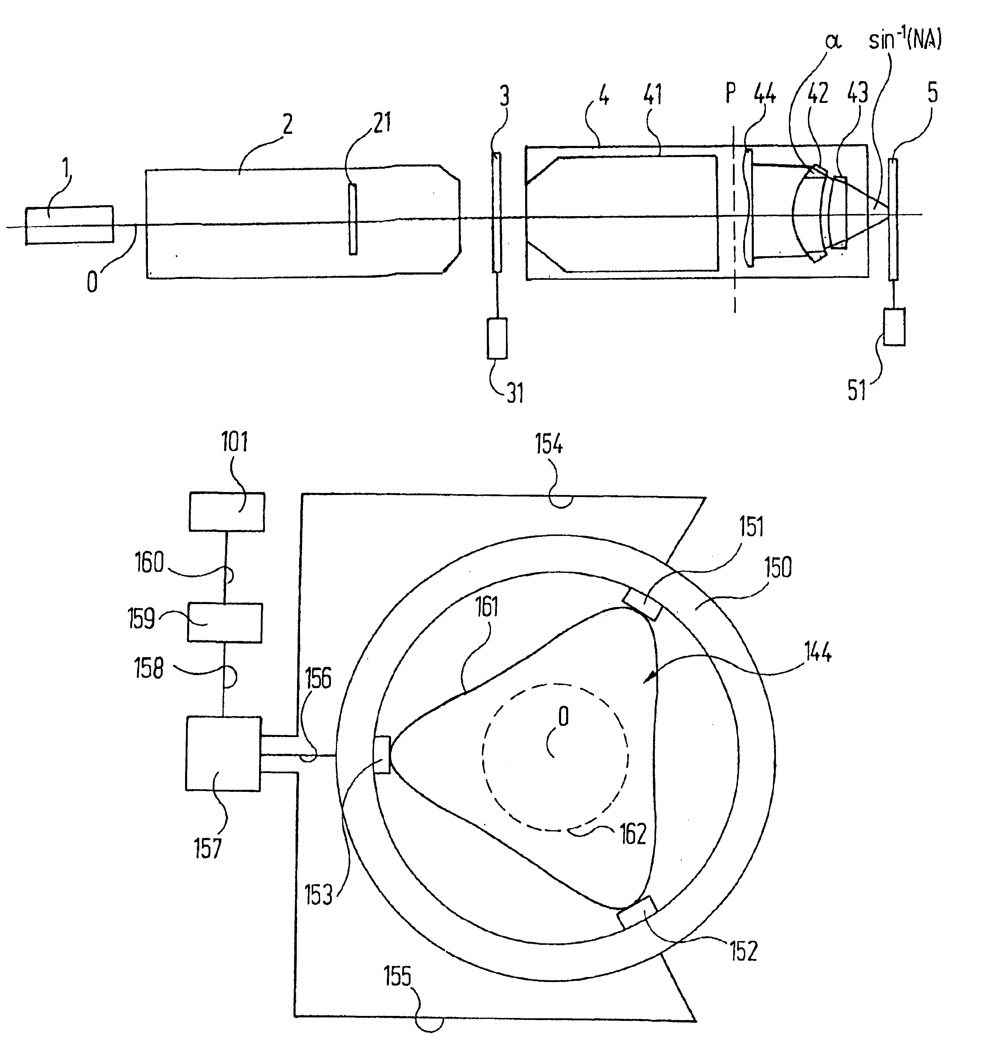
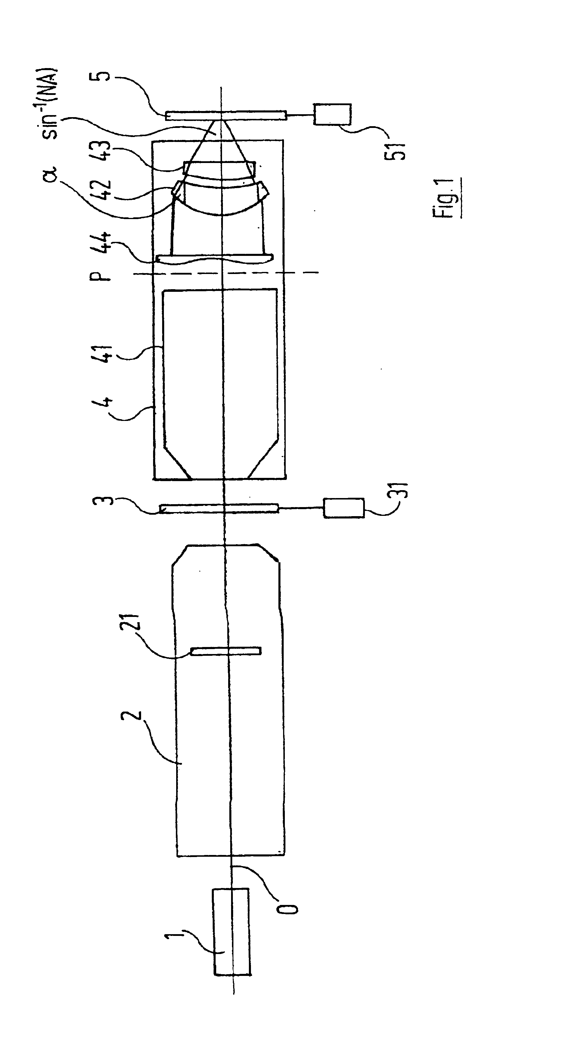
Arranged with respect to an optical axis O, FIG. 1 shows a light source 1, which is preferably a laser emitting with a narrow band at 157 nm or 193 nm. Its light is delivered to an illumination system 2 which, as a special feature, may contain means 21 for producing radial polarization, as are known from DE 195 35 392 A which is equivalent to U.S. Pat. No. 6,392,804. This is used to illuminate a reticle 3 which is connected to a reticle-holding and -positioning system 31. The subsequent projection lens 4 images the reticle 3 onto an object 5—typically a wafer—arranged in the image plane. The object 5 is provided with an object-holding and -positioning system 51.

The projection lens 4 comprises a group 41 of lenses and, if need be, also one or more mirrors, a pupil plane or system aperture plane P and, between this plane P and the plane of the object 5, lenses 42, 43 whose transmission angle a is determined by the numerical aperture NA on the image side of the projection lens.

At least...


PUM

PropertyMeasurementUnit
wavelengthaaaaaaaaaa
wavelengthsaaaaaaaaaa

Abstract

A projection exposure apparatus for microlithography has a light source, an illumination system, a mask-positioning system and a projection lens. The latter has a system aperture plane and an image plane and contains at least one lens that is made of a material which has a birefringence dependent on the transmission angle. The exposure apparatus further has an optical element, which has a position-dependent polarization-rotating effect or a position-dependent birefringence. This element, which is provided close to a pupil plane of the projection exposure apparatus, compensates at least partially for the birefringent effects produced in the image plane by the at least one lens.

Description

BACKGROUND OF THE INVENTION1. Field of the InventionThe invention relates generally to projection exposure apparatus and projections lenses used therein. Such apparatus are used for the microlithographic manufacture of electronic circuits and other microstructured devices.2. Description of Related ArtU.S. patent application Ser. No. 10 / 177 580 discloses purely refractive and catadioptric projection lenses, with numerical apertures of 0.8 and 0.9 at an operating wavelength of 157 nm, which are suitable for projection exposure apparatus known from the market.For projection wavelengths in the deep ultraviolet (DUV) fluoride crystals are used as material for lenses and other refractive optical elements. U.S. Pat. No. 6,201,634 B describes that technical fluoride crystals suitable for this use have stress birefringence which exhibits direction dependency with respect to the crystal axes.It is known from the Internet publication “Preliminary Determination of an Intrinsic Birefringence in ...

Claims


Application Information

Patent Timeline
Patent Type & Authority Patents(United States)
IPC IPC(8): G02B1/00G02B1/02G02B5/30G03F7/20G02B7/02H01L21/027
CPCG02B1/02G02B1/08G03F7/70966G03F7/70241G03F7/70825G02B5/3083G03B21/00
Inventor BRUNOTTE, MARTINHARTMAIER, JURGENHOLDERER, HUBERTKAISER, WINFRIEDKOHL, ALEXANDERKUGLER, JENSMAUL, MANFREDWAGNER, CHRISTIAN
Owner CARL ZEISS SMT GMBH
Why Eureka
Try Eureka