Eureka AIR delivers breakthrough ideas for toughest innovation challenges, trusted by R&D personnel around the world.

Draft inducer having single piece metal impeller and improved housing

Inactive Publication Date: 2005-04-19
REGAL BELOIT AMERICA
View PDF13 Cites 17 Cited by
  • Summary
  • Abstract
  • Description
  • Claims
  • Application Information

AI Technical Summary

Benefits of technology

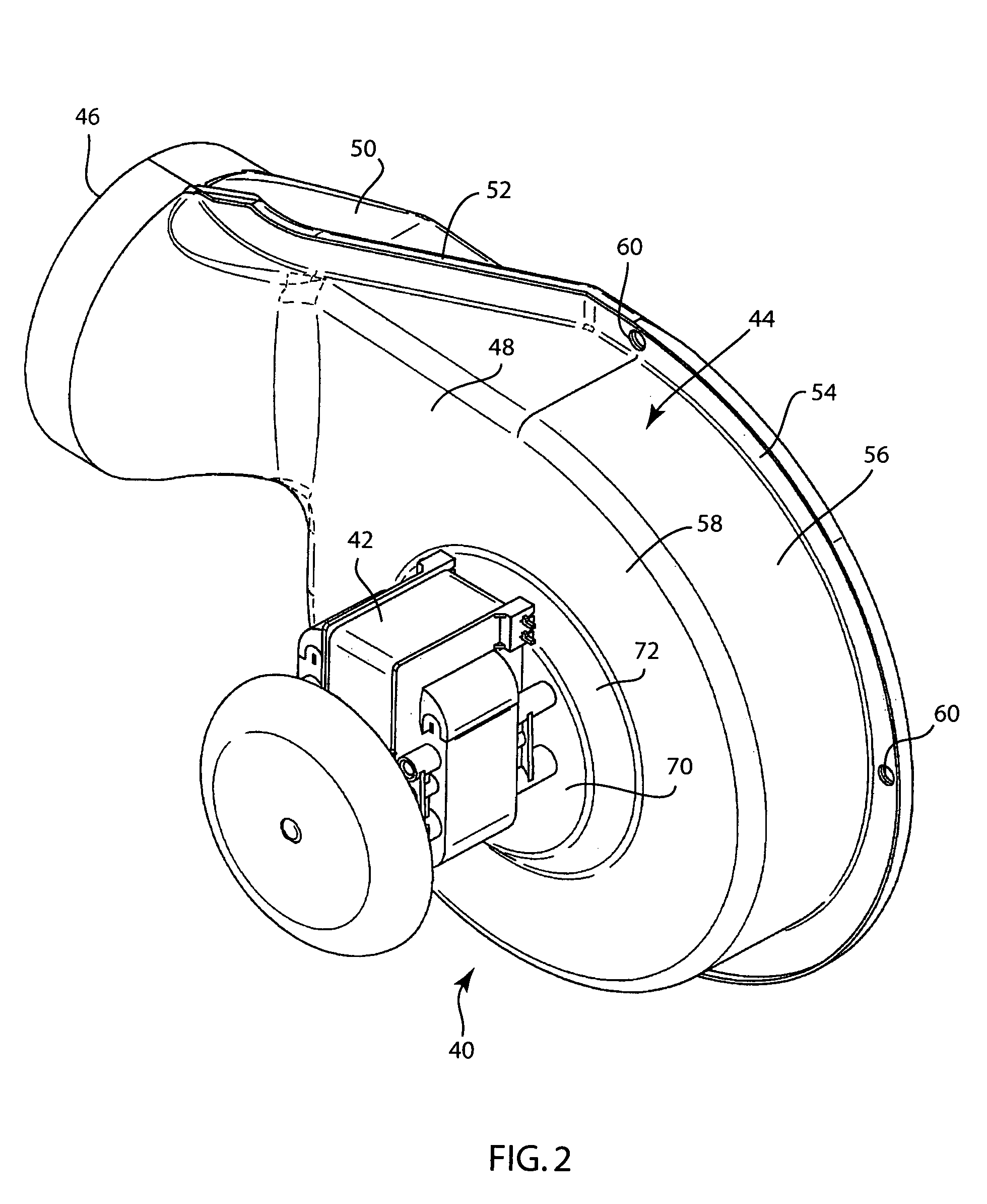
[0010]The drive shaft of the drive motor extends through the top wall of the raised plenum into the impeller cavity formed by the blower housing. In accordance with the present invention, a small opening or gap is formed in the top wall of the plenum surrounding the drive shaft. The gap allows the drive shaft to freely rotate and allows a small flow of ambient air to enter into the plenum cavity due to the negative pressure created by the rotating impeller within the impeller cavity. The small flow of ambient air into the plenum cavity creates a buffer of cooler air between the hot exhaust gases in the impeller cavity and the drive motor mounted to the exterior of the top wall of the plenum.
[0011]The buffer of cooler air contained in the plenum cavity allows the blower assembly of the present invention to eliminate the use of a slinger fan to create the similar buffer of air between the hot exhaust gases and the drive motor. The elimination of the slinger fan reduces the rotational load on the drive shaft, thereby allowing for a smaller drive motor to be used while generating the same operating efficiency for the impeller.
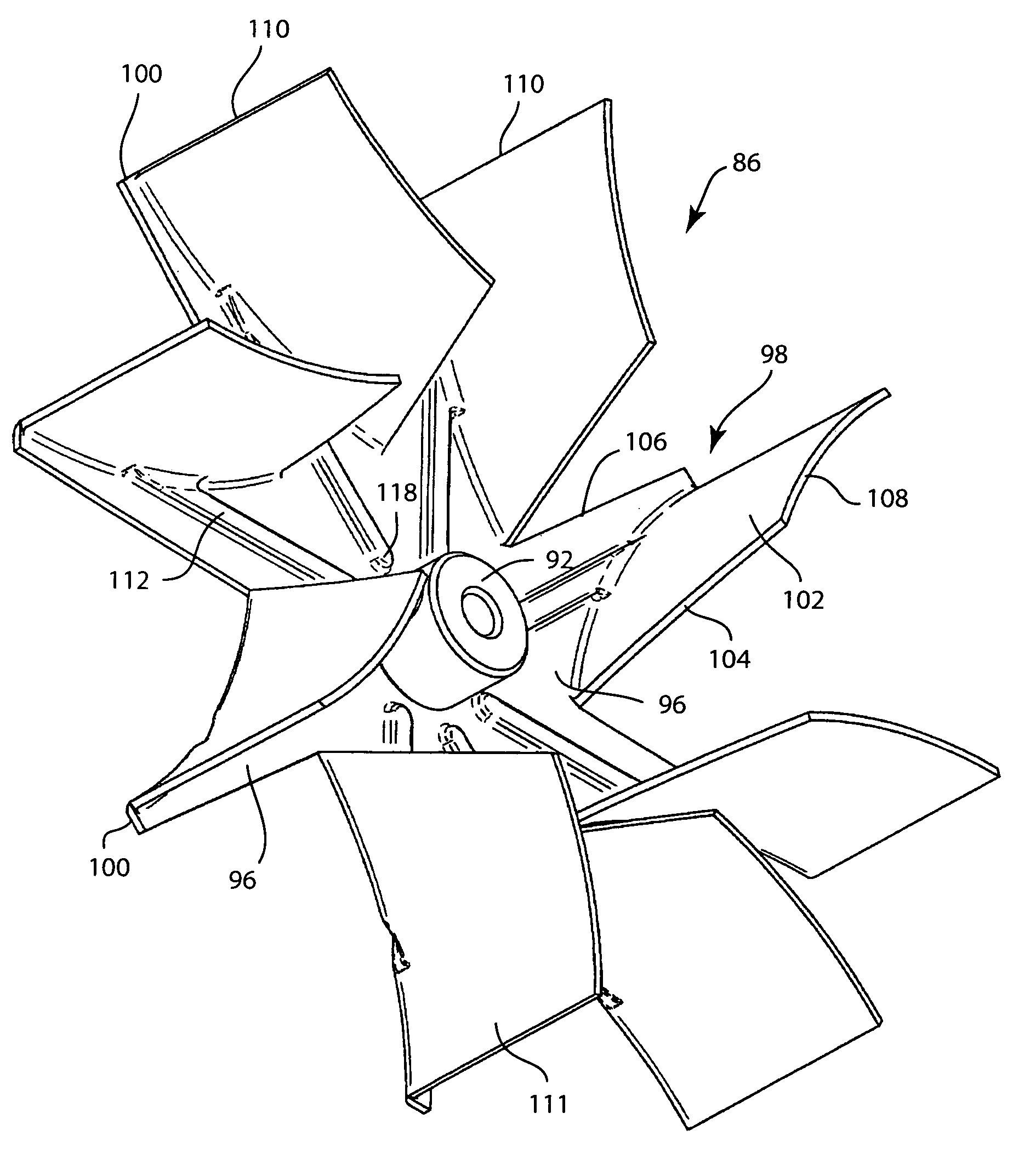
[0014]The air flow and static pressure in a blower assembly can be further increased by using a larger diameter impeller. In order to increase the impeller diameter and maintain the same overall housing size, it is necessary to reduce the housing diffuser (expansion) angle. A significant reduction of the diffuser angle greatly reduces the efficiency of a forward curved squirrel cage type impeller. Since a backward inclined (blade leading edge at impeller inlet) forward curved impeller develops most of its static pressure on its blades surfaces, it is therefore less dependent on the housing diffuser angle. A backward inclined forward curved impeller, such as the blower assembly of the present invention, can operate with high efficiency in a housing with little or no diffuser angle.
[0015]The back wall of the impeller includes a series of protruding ribs that are formed into the otherwise planar surface. Each of the ribs extends radially outward and is aligned with one of the impeller blades. The protruding ribs provide additional structural stability for each of the impeller blades.
[0016]As described above, the blower assembly of the present invention includes a single piece stamped impeller formed from sheet metal. The impeller includes backward inclined forward-curved impeller blades that increase the efficiency and operating characteristics of the blower as compared to prior art blowers utilizing single piece stamped sheet metal impellers having radial blades. Further, the blower assembly of the present invention includes a blower housing having a raised plenum that creates a buffer of air between the heated exhaust gases within the impeller cavity and the drive motor. The use of the raised plenum on the top wall of the blower housing allows for the elimination of a slinger fan, thereby reducing the load on the drive motor.

Problems solved by technology

Thus, the labor and material costs to produce a squirrel cage impeller are significant.
Although the radial blade, one-piece sheet metal impeller reduces the cost of producing the impeller as compared to a squirrel cage impeller, the performance characteristics of the currently available single piece stamped sheet metal impellers do not meet current performance standards and thus has limited the use of such impellers in blower assemblies.
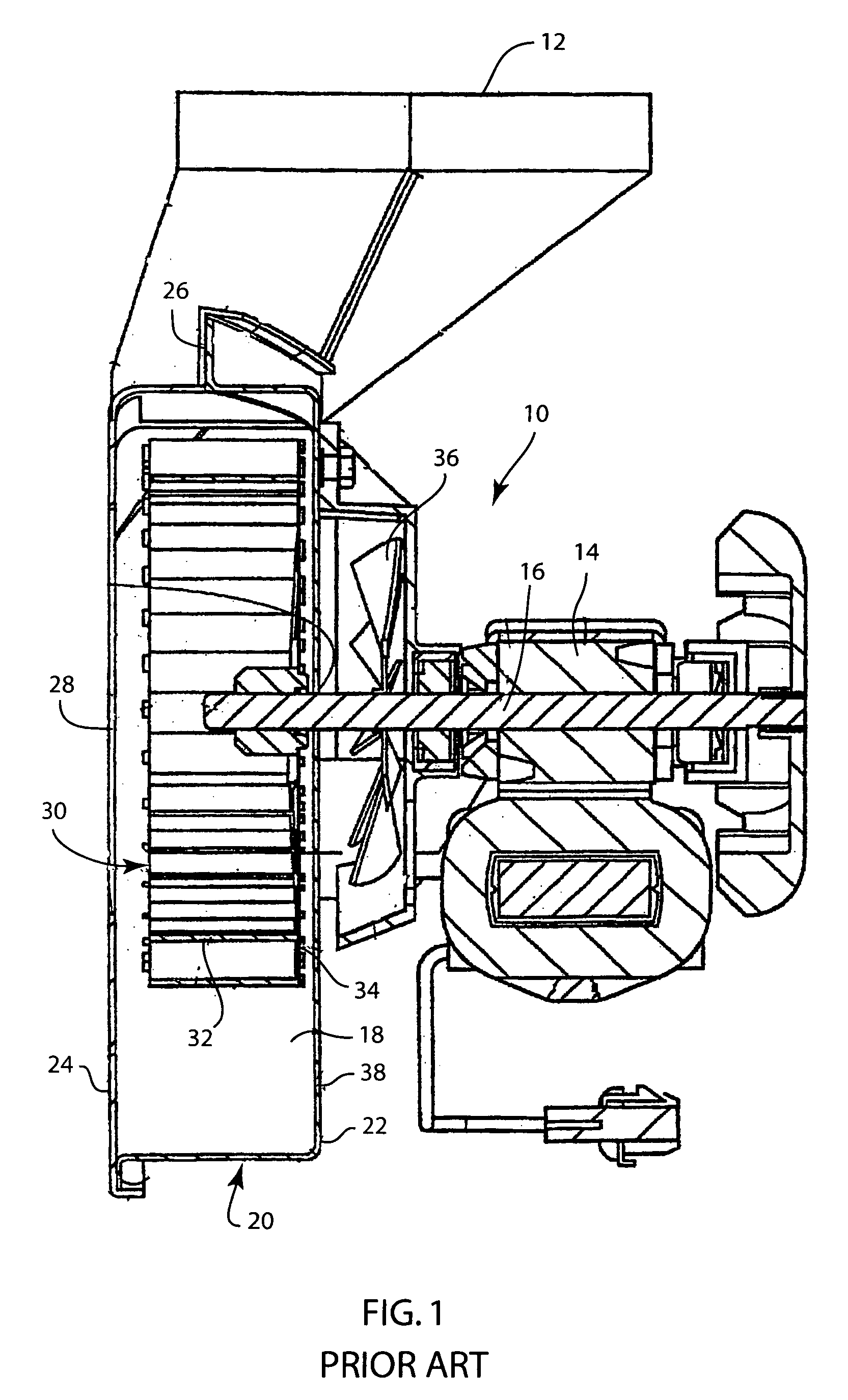
Although the slinger fan creates the desired cooling effect, the slinger fan increases the drag on the rotation of the motor shaft and thus requires a larger motor size to create the desired air flow characteristics by the impeller included in the impeller cavity of the blower assembly.
Further, the slinger fan increases the material and assembly costs of the blower assembly.

Method used


Image

  • Draft inducer having single piece metal impeller and improved housing
  • Draft inducer having single piece metal impeller and improved housing
  • Draft inducer having single piece metal impeller and improved housing

Examples


Embodiment Construction

[0029]Referring first to FIG. 1, thereshown is a prior art blower assembly 10. The blower assembly 10 is used on an 80+ furnace to expel exhaust gases from the furnace out through an exhaust outlet 12 that is connected to a flue pipe (not shown) for directing the exhaust gases out of the building in which the furnace is located. The prior art blower assembly 10 includes a drive motor 14 having a drive shaft 16 that extends into the impeller cavity 18 formed by the blower housing 20. In the embodiment of the invention illustrated, the blower housing 20 is formed from a pair of stamped sheet metal housing sections 22 and 24 joined to each other along a cinch seam 26.

[0030]The blower housing 20 includes an inlet opening 28 that allows exhaust gases to flow into the impeller cavity due to the rotation of the impeller 30. As illustrated in FIG. 1, the impeller 30 is a conventional squirrel cage impeller having a plurality of forward curved impeller blades 32 each attached to a back plate...


PUM


Abstract

A furnace blower assembly having a single piece impeller formed from a stamped metal material. The impeller of the blower assembly is formed from a single piece of metal material and includes a plurality of individual impeller blades each having a blade portion bent at a 90° angle relative to the back wall of the impeller. Each of the impeller blades is backward inclined and forward curved to increase the efficiency of the impeller.

Description

FIELD OF THE INVENTION[0001]The present invention generally relates to a blower housing and impeller for use in a blower assembly used to withdraw exhaust gases from a furnace. More specifically, the present invention relates to a one-piece stamped metal impeller design having backward inclined forward curved (cupped in the direction of rotation) impeller blades for use in a blower to decrease the cost of the blower while maintaining the desired efficiency and air flow characteristics.BACKGROUND OF THE INVENTION[0002]The need to heat structures to control the interior temperature has been a requirement for modern housing for many years. One of the current popular methods to heat a structure is with a furnace that burns either oil or natural gas. Due to the increasing cost of fossil fuels, the operating efficiency of such furnaces has become a greater and greater concern.[0003]One common method of increasing the fuel efficiency of a burner within a furnace has been to utilize a blowe...

Claims


Application Information

Patent Timeline
IPC IPC(8): F01D25/24F01D5/14F01D25/26F04D29/28
CPCF01D5/14F04D29/282F01D25/265Y10S416/03
Inventor PAULSEN, FREDERICK D.
Owner REGAL BELOIT AMERICA
Why Eureka
Eureka Blog
Learn More