Air-tight vessel equipped with gas feeder uniformly supplying gaseous component around plural wafers

a gas feeder and air tight technology, applied in the direction of lighting and heating apparatus, muffle furnaces, furnaces, etc., can solve the problems of reduced zone available for single chemical vapor deposition, different reduced thickness of deposited substance layers, etc., to achieve high productivity

Inactive Publication Date: 2005-04-19
NEC ELECTRONICS CORP
View PDF17 Cites 60 Cited by
  • Summary
  • Abstract
  • Description
  • Claims
  • Application Information

AI Technical Summary

Benefits of technology

[0013]It is therefore an important object of the present invention to provide a deposition system, a reactor of which permits subs

Problems solved by technology

A problem is encountered in the prior art reactor in that the layers of deposited substance are different in thickness.
This results in the difference in thickness.
This results in reduction in the zone available for a single chemical vapor deposition.
However, a problem is encountered in the prior art chemical vapor deposition reactor due to the gas outlet holes 9a/9b.
The small holes are much more liable to

Method used


Image

  • Air-tight vessel equipped with gas feeder uniformly supplying gaseous component around plural wafers
  • Air-tight vessel equipped with gas feeder uniformly supplying gaseous component around plural wafers
  • Air-tight vessel equipped with gas feeder uniformly supplying gaseous component around plural wafers

Examples


Embodiment Construction

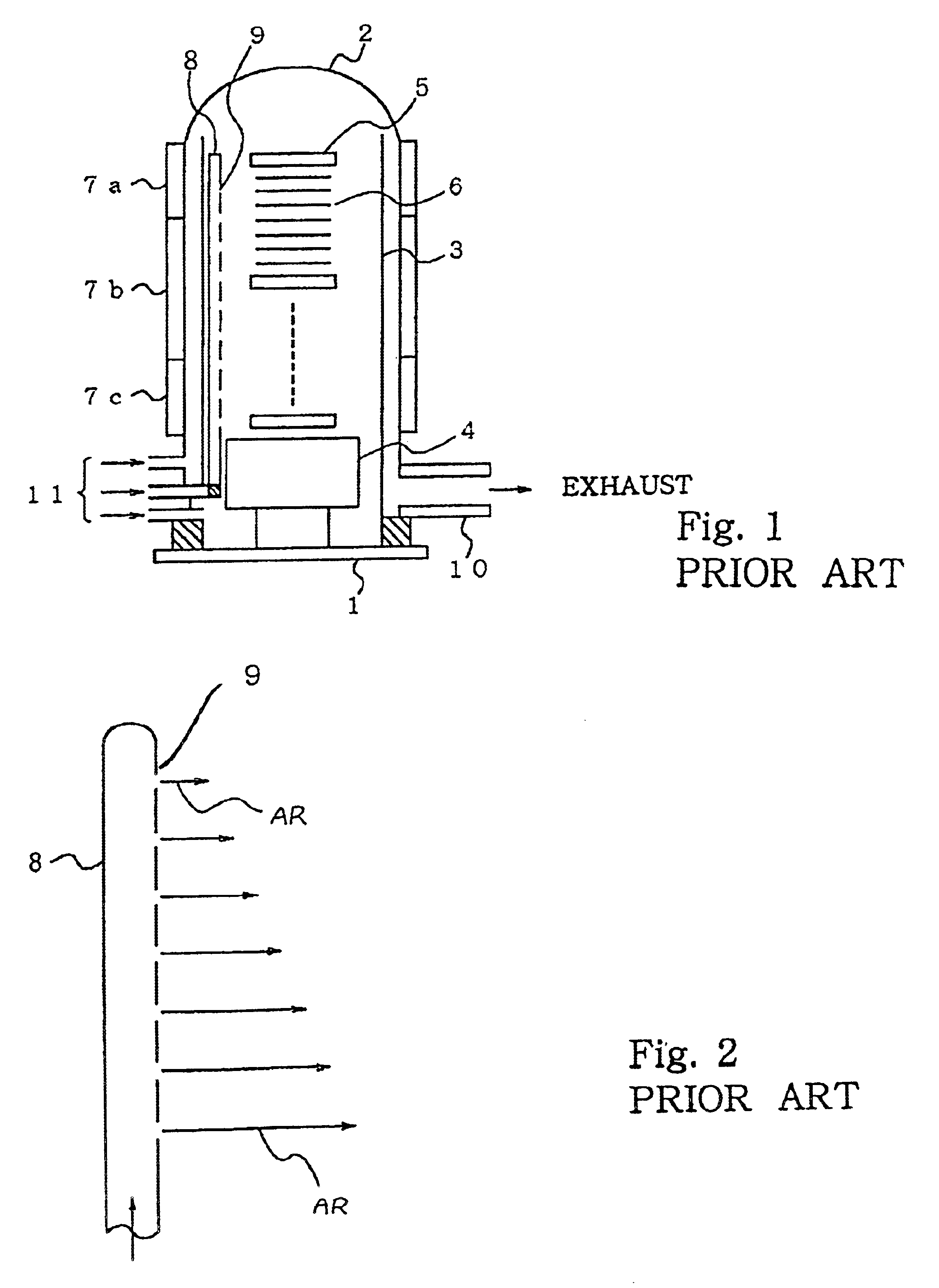
[0026]Referring to FIG. 4 of the drawings, a vertical low-pressure chemical vapor deposition system largely comprises a gas supply system, a vertical reactor and an exhaust system. The gas supply system includes sources of gas such as N2, TMOB or PH3 and TEOS and gas supply pipes 11, and these kinds of gas are supplied through the supply pipes 11 to the reactor. On the other hand, the exhaust system includes an exhaust pipe 10, a pressure regulator (not shown) and a source of vacuum (not shown) such as, for example, a vacuum pump, and the exhaust system keeps the gas pressure inside of the reactor substantially constant.

[0027]Doping gas, dilution gas and reactant gas are supplied from the gas supply system to the reactor. The doping gas may be boron trimethyl ester TMOB or phosphine PH3. The dilution gas may be nitrogen, and the reactant gas for deposited material may be tetraethylorthosilicate TEOS.

[0028]The reactor includes a base structure 1. The base structure 1 is broken down i...


PUM

PropertyMeasurementUnit
Shapeaaaaaaaaaa

Abstract

A reactor of a chemical vapor deposition system is equipped with a gas feeder for blowing dopant gas to plural semiconductor wafers supported by a wafer boat at intervals, and the gas feeder has a gas passage gradually reduced in cross section and gas outlet holes equal in diameter and arranged along the wafer boat for keeping the doping gas concentration substantially constant around the semiconductor wafers, whereby the dopant is uniformly introduced in material deposited on all the semiconductor wafers.

Description

FIELD OF THE INVENTION[0001]This invention relates to a gas treatment system and, more particularly, to a reactor or furnace incorporated in a gas treatment system used in the semiconductor manufacturing field.DESCRIPTION OF THE RELATED ART[0002]A vertical low-pressure chemical vapor deposition system is popular to the semiconductor manufacturers. FIG. 1 shows a typical example of the vertical low-pressure chemical vapor deposition system. A reactor and a gas supply system (not shown) are incorporated in the prior art vertical low-pressure chemical vapor deposition system.[0003]The prior art reactor includes a base 1, an outer tube 2 and an inner tube 3. The base 1 is fixed to a horizontal foundation (not shown), and is upright thereon. The outer tube 2 is open at one end thereof, and is closed at the other end. The outer tube 2 is larger in diameter than the inner tube 3, and is longer than the inner tube 3. The inner tube 3 is open at both ends thereof. Gas inlet ports are formed ...

Claims


Application Information

Patent Timeline
IPC IPC(8): C23C16/40C23C16/455C23C16/44H01L21/205F27B5/16F27D7/02H01L21/22H01L21/31
CPCC23C16/401C23C16/45578C23C16/45563C23C16/455C23C16/45574
Inventor NAGAKURA, YUTAKA
Owner NEC ELECTRONICS CORP
Why Eureka
Try Eureka