

Capacitive type sensor
a capacitive type, sensor technology, applied in the direction of fixed capacitor details, fixed capacitors, instruments, etc., can solve the problems of large size, failure to meet the demand of compactness of sensors, and error in humidity measurement, so as to increase the strength of electrodes to the insulating substrate
- Summary
- Abstract
- Description
- Claims
- Application Information
AI Technical Summary
Benefits of technology
Problems solved by technology
Method used
Image

Examples
example 1
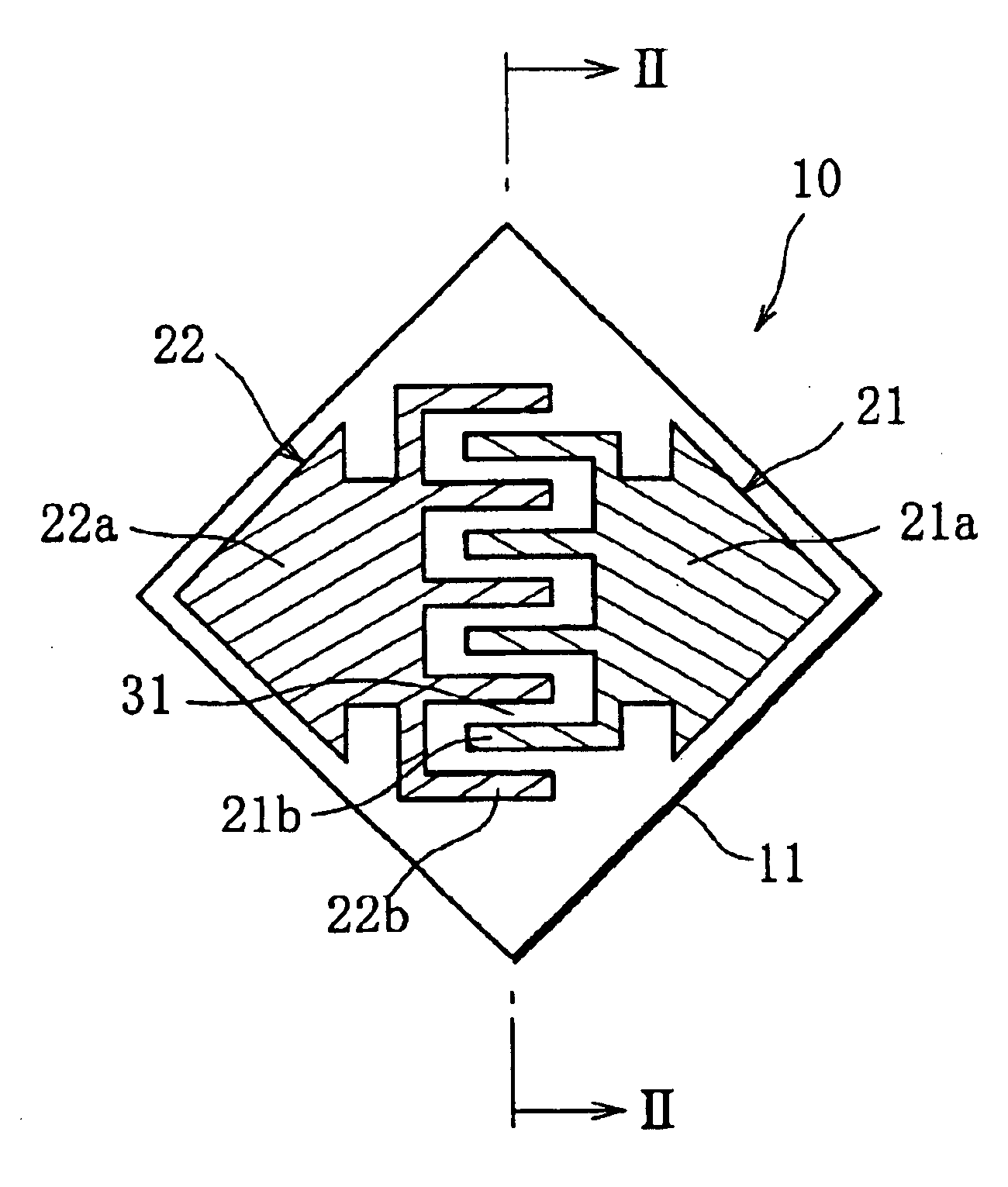
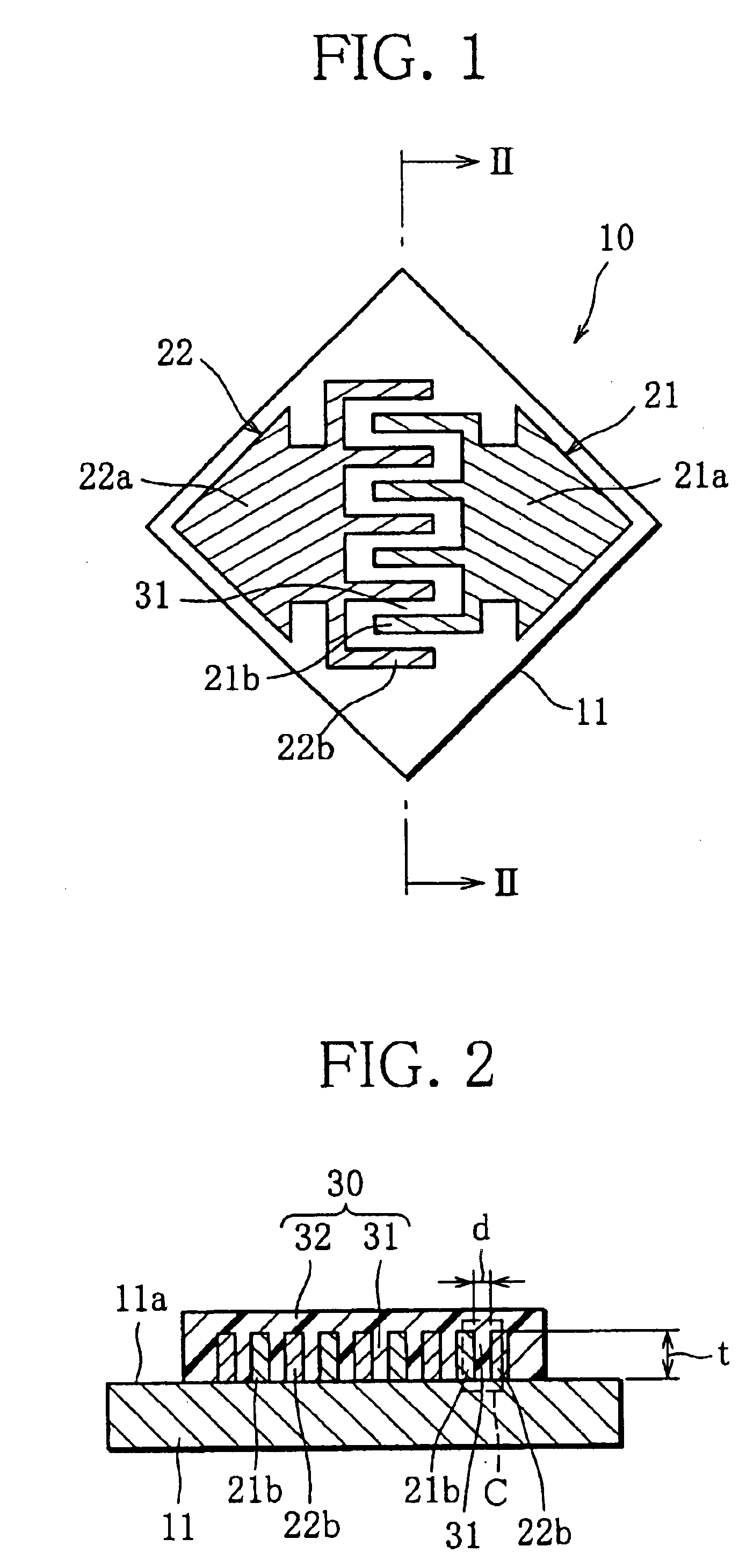
[0087]A plurality of capacitive type sensors of Example 1, each corresponding to the sensor 10 shown in FIGS. 1 and 2, were fabricated as described below.
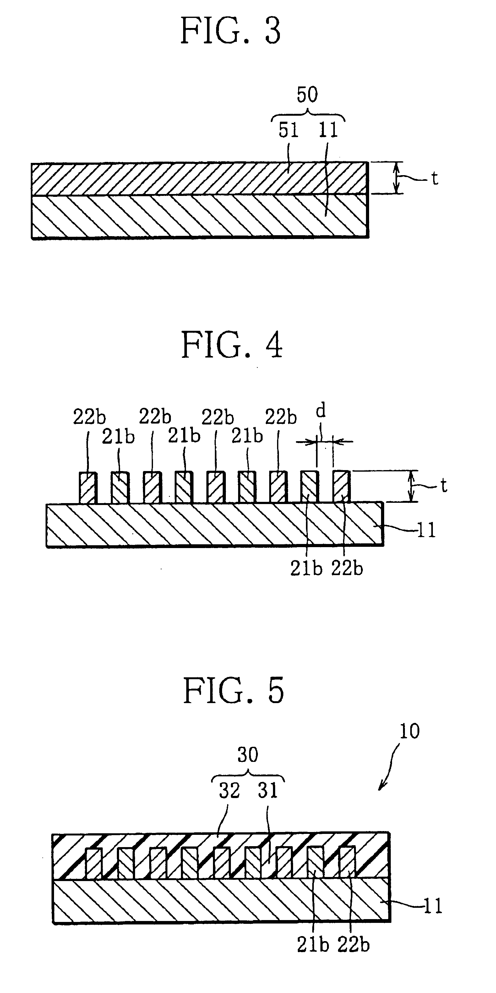
[0088]First, SOI substrates were prepared, each having a glass substrate serving as an insulating substrate 11, and an Si wafer joined to one surface of the glass substrate and serving as an electrically conductive substrate. Next, the Si wafers of the SOI substrates were subject to polishing, thus obtaining starting substrates 50 (refer to FIG. 3) provided with Si thin films that are different in thicknesses (electrode thickness t). The Si thin films of the starting substrates 50 were subject to ICP etching, whereby electrodes 21, 22 having comb-electrode portions 21b, 22b whose face-to-face distance was 5 μm were formed on the insulating substrate 11 (refer to FIG. 4). Polyimide-based resin liquid serving as a material for water vapor sensitive film was applied onto the electrodes 21, 22, and the resultant product was subject to ...
example 2
[0092]A number of capacitive type sensors of Example 2 (corresponding to the sensor 10 shown in FIGS. 1, 2) were fabricated in the same manner as the sensors of Example 1. In the fabrication of these sensors, the electrode thickness t remained constant at 5 μm, whereas the face-to-face distance d of comb-electrode portions 21b, 22b were varied in a range from about 0.3 μm to 5 μm. The distances d were at about 0.3 μm, 0.5 μm, 1 μm, 1.2 μm, 2 μm, 3 μm, 4 μm, and 5 μm.
[0093]The capacitive type sensors having been fabricated were divided into groups depending on the face-to-face distance d, and the sensors were divided into acceptable products without a failure in the water vapor sensitive film and faulty products with such a failure. Then, the fabrication yield for each sensor group was determined from a ratio of the number of acceptable products belonging to the sensor group to the total number of sensors belonging thereto). FIG. 12 shows relative fabrication yields for respective di...
example 3
[0095]A capacitive type sensor of Example 3, corresponding to the sensor 10A shown in FIG. 6, was fabricated by using an SOI substrate, and by using polyimide as a material for water vapor sensitive film. The capacitive type sensor was 5 μm in both the thickness and face-to-face distance of comb-electrode portions, and 3 μm in thickness of an upper water vapor sensitive film in which a shielding film made of Cr and having a thickness of 2000 angstroms was provided.
[0096]First to fifth standard environments were prepared that were at a temperature of 25 degree centigrade and at relative humidities of, e.g., 10%, 25%, 45%, 70% and 90%, respectively, for instance. Next, the capacitive type sensor of Example 3 was placed in the first standard environment, and the sensor's capacitance C10 was measured. Subsequently, the sensor was left for 200 hours in a higher temperature / humidity environment at a temperature of 40 degree centigrade and a relative humidity of 90%, was returned to the fi...
PUM
 Abstract
Description
Claims
Application Information