Variable oscillation frequency resonance circuit and voltage controlled oscillator using the same

a frequency resonance circuit and frequency technology, applied in the field of oscillators, can solve the problems of deteriorating phase noise characteristics and deteriorating quality factors, and achieve the effects of improving high frequency characteristics, reducing resistance within resonance circuits, and increasing quality factors

Inactive Publication Date: 2005-04-19
SAMSUNG ELECTRO MECHANICS CO LTD
View PDF3 Cites 20 Cited by
  • Summary
  • Abstract
  • Description
  • Claims
  • Application Information

AI Technical Summary

Benefits of technology

[0022]Accordingly, the present invention has been made keeping in mind the above problems occurring in the prior art, and an object of the present invention is to provide a variable oscillation frequency resonance circuit and voltage controlled oscillator using the same, which reduces resistance within a resonance circuit in a voltage controlled oscillator for oscillating at frequencies in a wide-band, thus improving high frequency characteristics, and increasing the quality factor to improve phase noise characteristics.

Problems solved by technology

However, in the conventional construction as shown in FIG. 4, two switching transistors connected as one pair on the basis of the output terminals A and B are connected in series with respective capacitors, so the total resistance Re|z| is increased to deteriorate the quality factor Q. Further, phase noise characteristics may be deteriorated due to the deterioration of the quality factor Q.

Method used


Image

  • Variable oscillation frequency resonance circuit and voltage controlled oscillator using the same
  • Variable oscillation frequency resonance circuit and voltage controlled oscillator using the same
  • Variable oscillation frequency resonance circuit and voltage controlled oscillator using the same

Examples


Embodiment Construction

[0037]Hereinafter, a variable oscillation frequency resonance circuit and voltage controlled oscillator using the same according to embodiments of the present invention will be described in detail with reference to the attached drawings.

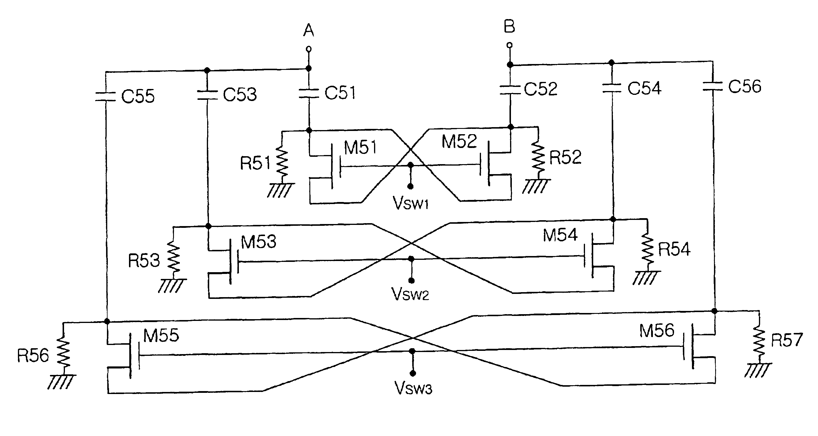
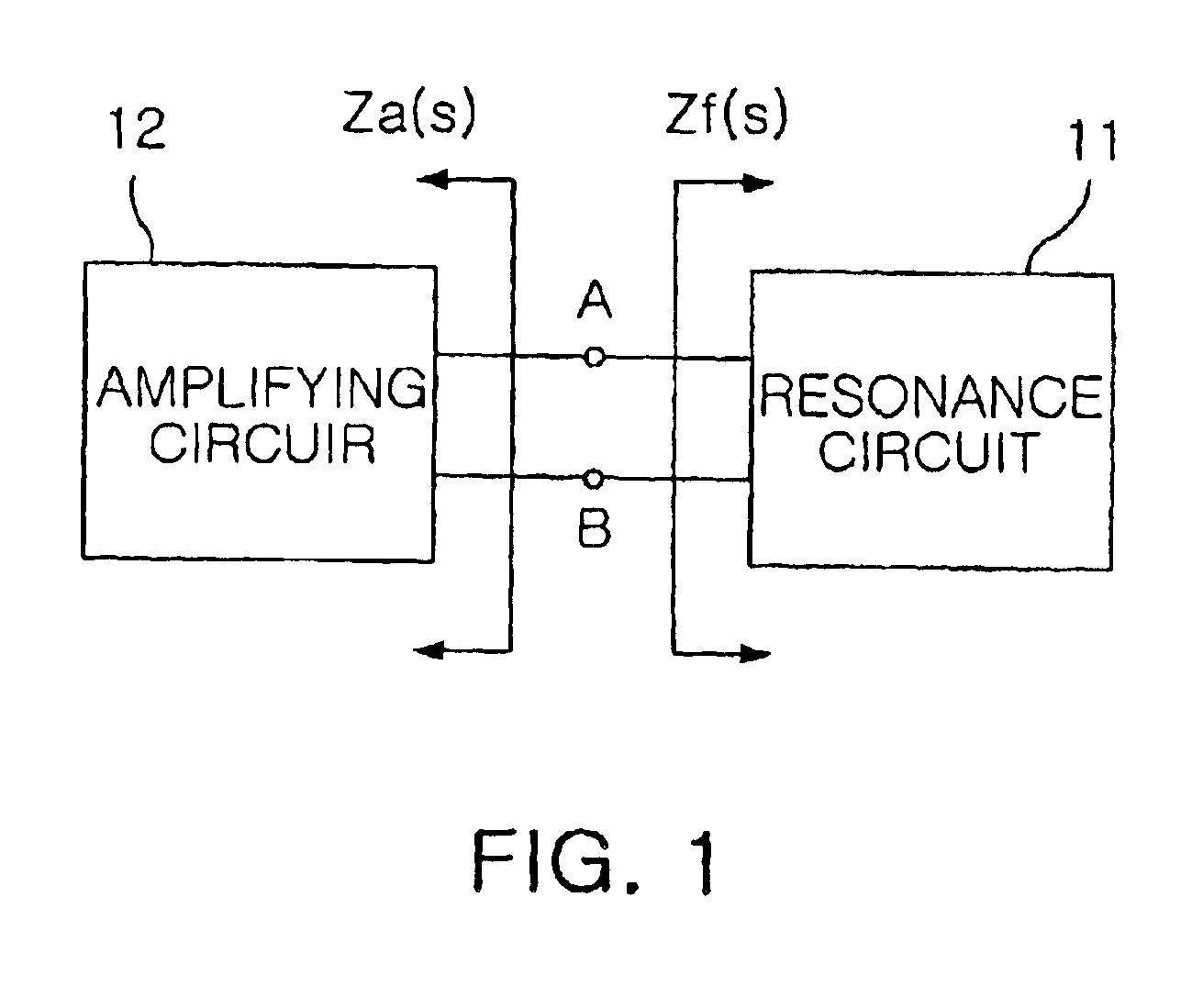
[0038]FIG. 5 is a circuit diagram of an oscillation frequency varying circuit according to an embodiment of the present invention. The circuit comprises a plurality of capacitance element pairs C51-C52, C53-C54 and C55-C56, a plurality of differential switching element pairs M51-M52, M53-M54 and M55-M56, and a plurality of first and second resistor pairs R51-R52, R53-R54, and R55-R56. The capacitance element pairs C51-C52, C53-C54 and C55-C56 have one ends connected to the output terminal A or B connected to the inductance element L21 in the amplifying circuit 12 as shown in FIG. 1 and the resonance circuit 11 as shown in FIG. 2. The differential switching element pairs M51-M52, M53-M54 and M55-M56 are each arranged between two capacitance elements o...


PUM


Abstract

The present invention relates to a variable oscillation frequency resonance circuit and voltage controlled oscillator using the same, which includes an inductance element, frequency varying means, and oscillation band varying means. The oscillation band varying means is provided with one or more capacitance element pairs and one or more differential switching element pairs each being arranged between capacitance elements of each of the capacitance element pairs, with differential switching elements of each of the differential switching element pairs being arranged in parallel with each other, to allow a corresponding capacitance element pair to be connected to the inductance element in response to second control signals.

Description

BACKGROUND OF THE INVENTION[0001]1. Field of the Invention[0002]The present invention relates generally to an oscillator for generating frequencies ranging over a wide-band and, more particularly to a variable oscillation frequency resonance circuit and voltage controlled oscillator using the same, which increases the quality factor of the resonance circuit and improves phase noise characteristics by reducing the impedance of switching elements at the time of selecting an oscillation band.[0003]2. Description of the Prior Art[0004]Generally, an oscillator generates a signal with a specific frequency in an electrical circuit. As shown in FIG. 1, an oscillator is generally comprised of a resonance circuit 11 for resonating with a signal with a specific frequency, and an amplifying circuit 12 for continuously supplying the signal with the specific frequency resonated by the resonance circuit 11. Further, the resonance circuit for determining the specific frequency is implemented by an ...

Claims


Application Information

Patent Timeline
Patent Type & Authority Patents(United States)
IPC IPC(8): H03B5/08H03B5/12H03B1/00
CPCH03B5/1225H03B5/1228H03B5/1293H03B5/1243H03B5/1265H03B5/1212H03B2201/0208H03B5/08
Inventor OH, SEUNG MINKWON, HYO SEOK
Owner SAMSUNG ELECTRO MECHANICS CO LTD
Why Eureka
Try Eureka