Geopositionable expendable sensors and the use therefor for monitoring surface conditions

a technology of expendable sensors and geoposition, which is applied in the direction of instruments, electric signalling details, cosmonautic vehicles, etc., can solve the problems of overpowering the terrorist's ability to find and destroy all sensor pods, and achieves the effects of reducing sensitivity, increasing variety, and quick geoposition mapping

Inactive Publication Date: 2005-04-26
COOPER GUY F +4
View PDF7 Cites 29 Cited by
  • Summary
  • Abstract
  • Description
  • Claims
  • Application Information

AI Technical Summary

Benefits of technology

[0004]The invention provides a system for detecting and geopositioning data samples of trace materials associated with biological, chemical, or radioactive conditions, as well as localized environmental conditions on a surface including vibrations and radio emissions utilizing a number of small, preferably inexpensive and expendable telemetering sensors, that are sown over a surface to be monitored by aircraft. The telemetered data signals avoid the problem of range attenuation (by the inverse range squared) of any radiation manifested by trace conditions being detected.
[0005]The sensor pods of the invention permit rapid geoposition mapping of trace biological, chemical, or radioactive warfare contaminant agents over large areas of terrain from a standoff distance. Other variables, such as sounds and vibrations, can also be detected. Thus, the sensor pod deploying platform, e.g. an aircraft or airborne pod, can be used to analyze a large area of terrain from a desired low, medium, high, or very high altitude. This analysis can be done quickly, and possibly as rapidly as a return flight over the

Problems solved by technology

In the case of monitoring for weapons of mass destruction (WMD) by a terrorist state or organization, an un-piloted dron

Method used


Image

  • Geopositionable expendable sensors and the use therefor for monitoring surface conditions
  • Geopositionable expendable sensors and the use therefor for monitoring surface conditions
  • Geopositionable expendable sensors and the use therefor for monitoring surface conditions

Examples


second embodiment

[0030]FIG. 7 is a perspective view of a sensor pod 80 with dipole antennas 82 and with reagent ports 83 and coaxial fiber optics 84 extending from exterior walls 86.

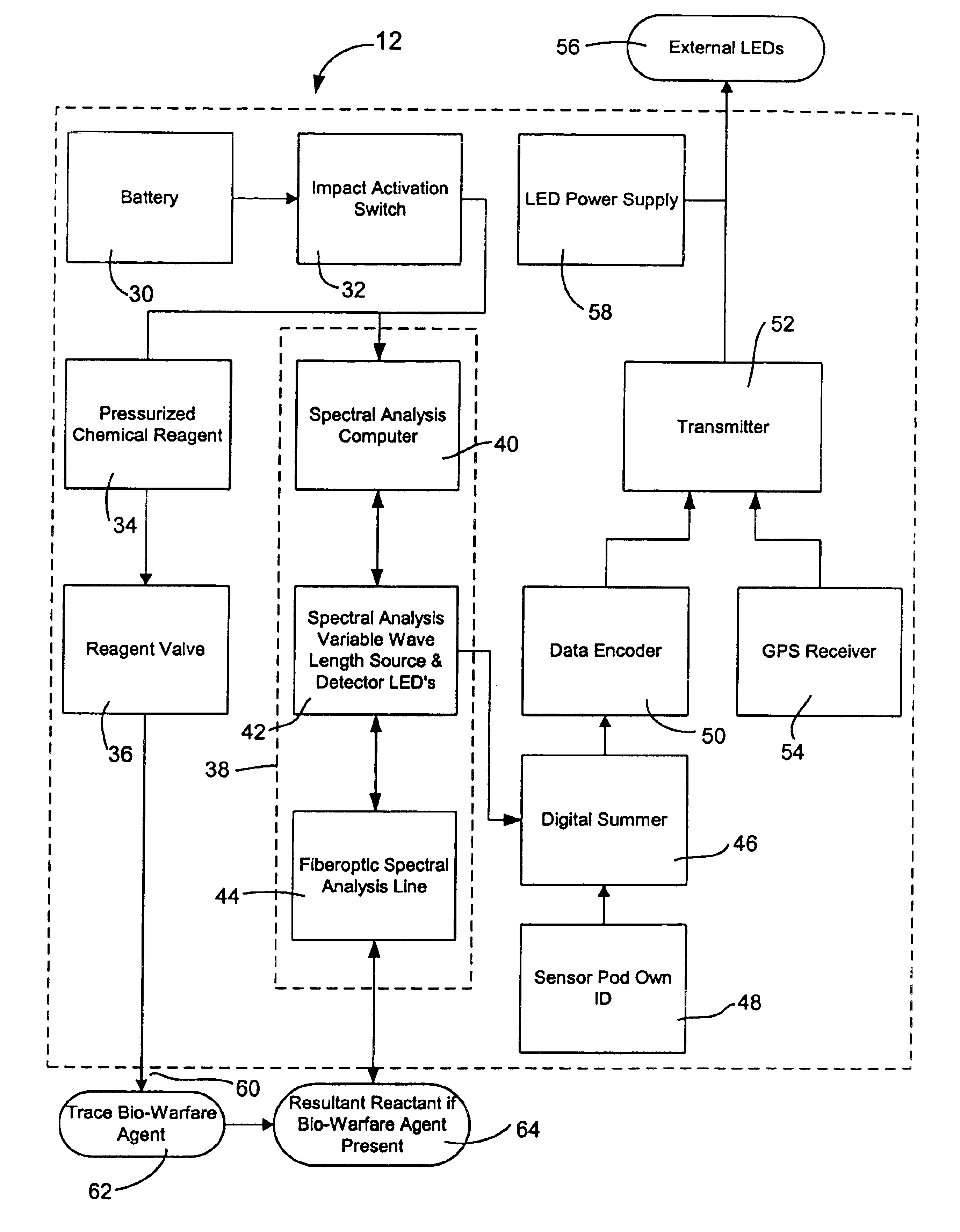
[0031]FIG. 8 is a diagram showing the internal systems of the second embodiment of the sensor pod 80 of FIG. 7, wherein dipole antennas 82 which are extendable beyond the sides 86 of the sensor pod 80. The dipole antennas 82 preferable extend from all sides of the sensor pod 80, which in the case of a generally cubic shape require six antennas. The dipole antennas 82 are used to transmit data. In other respects, the sensor pod 80 is similar to the sensor pod 12 of FIGS. 3 and 4. The sensor pod 80 includes a power supply, such as a battery 30, an impact activation switch 32, and pressurized chemical reagent 34 and a reagent valve 36. Contained in a spectral analysis unit 38, there is a spectral analysis computer 40, a spectral analysis variable spectral source and detector LEDs 42 and a fiberoptic spectral line analyzer l...

third embodiment

[0034]FIG. 10 is a diagram showing the internal systems of a sensor pod 100 for detection of radiation. The radiation detecting sensor pod 100 includes a power supply, such as a battery 102, an impact activation switch 104, and a radiation detection unit 106, which can comprise a gamma ray detector, a neutron flux detector, a charged particle detector and / or a thermoluminescent detector, for example. The radiation detection unit 106 communicates with a A / D conversion unit 108, which in turn communicates with a digital summer 110. The sensor pod ID code 112 is optionally loaded into the digital summer 110, and the data is further encoded, and possibly encrypted, by a data encoder 114. The data encoder 114 is connected to a transmitter 116. A global position system (GPS) recorder unit 118 with a power supply 120 is also connected to the transmitter 116, which uploads the data from the data encoder 114 and the GPS receiver 118 to the transmitter 116, which data is uploaded by a data up...


PUM


Abstract

A sensor system for monitoring for the presence of contamination with one or more contaminating biological, chemical and/or radioactive agents on a terrain surface, and creating a contamination map thereof. The sensor system includes a plurality of sensor pods, a ground station, an airborne dispensing portion, and an airborne monitoring portion. The sensor pods include a pod housing, a descent slowing airfoil, a detector unit for detection of the contaminating agent and outputting contaminating agent data, a processor for processing the contaminating agent data, a GPS unit for determining the position of the sensor, and a transmitter for transmitting contamination agent data and position data to the airborne monitoring portion. The airborne monitoring portion receives the transmitted data from the sensor pods, and relays the data to the ground station, where the contamination map is made available.

Description

CROSS-REFERENCE TO RELATED APPLICATIONS[0001]This utility patent application is based upon provisional patent application No. 60 / 383,082, filed May 24, 2002, with the same title “GEOPOSITIONABLE EXPENDABLE SENSORS AND THE USE THEREFOR FOR MONITORING SURFACE CONDITIONS.”BACKGROUND OF THE INVENTION[0002]The invention relates to devices and systems for detecting trace materials associated with biological, chemical, or radioactive conditions on a terrain surface, as well as localized environmental conditions, including vibrations and radio emissions, and more particularly to expendable sensors with telemetry capabilities which can be dropped from an airborne platform and later monitored from that platform or another platform to determine conditions at the site where the sensors have been deposited and / or in the vicinity thereof.[0003]There are numerous situations where it is desirable to map and monitor trace biological, chemical, radioactive agents, as well as localized environmental c...

Claims


Application Information

Patent Timeline
IPC IPC(8): G08B21/00G08B21/10G08B21/12
CPCG08B21/12G08B21/10
Inventor COOPER, GUY F.WILLIAMS, JOHN H.LEACH, MARKGRACE, DAVE J.VONWICKLEN, WILLIAM E.
Owner COOPER GUY F
Why Eureka
Try Eureka