Carbon wire heating object sealing heater and fluid heating apparatus using the same heater

a technology of heating object and sealing heater, which is applied in the direction of stoves, household stoves or ranges, semiconductor/solid-state device details, etc., can solve the problems of deteriorating semiconductor performance, generating metallic contamination, and further contaminating wafers, so as to improve the gas residence property

a technology of heating object and sealing heater, which is applied in the direction of stoves, household stoves or ranges, semiconductor/solid-state device details, etc., can solve the problems of deteriorating semiconductor performance, generating metallic contamination, and further contaminating wafers, so as to improve the gas residence property

US6885814B2Inactive Publication Date: 2005-04-26TOKYO ELECTRON LTD +1

Image

  • Carbon wire heating object sealing heater and fluid heating apparatus using the same heater
  • Carbon wire heating object sealing heater and fluid heating apparatus using the same heater
  • Carbon wire heating object sealing heater and fluid heating apparatus using the same heater

Examples


example

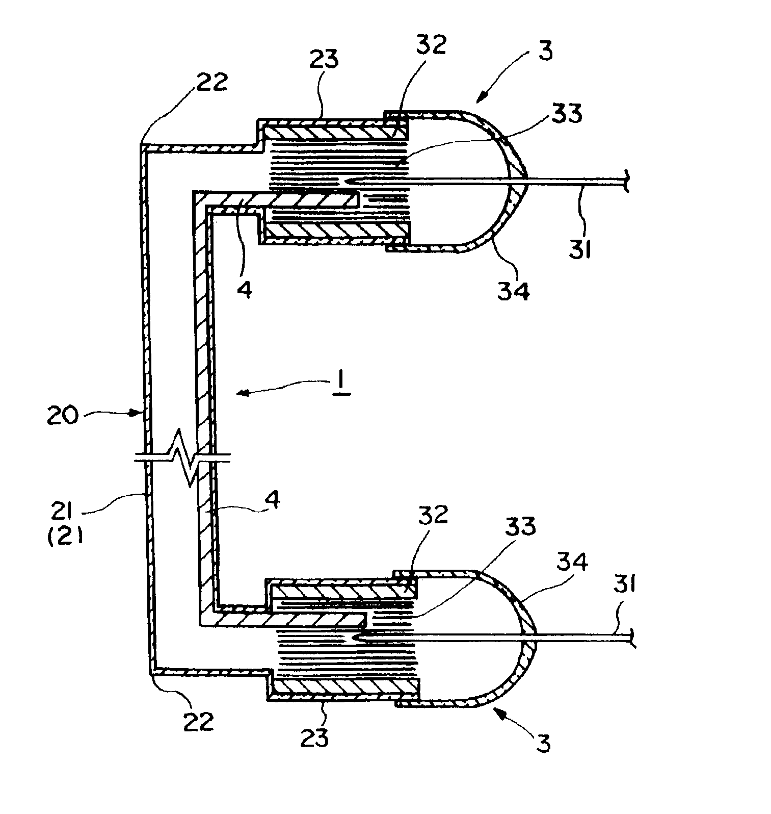
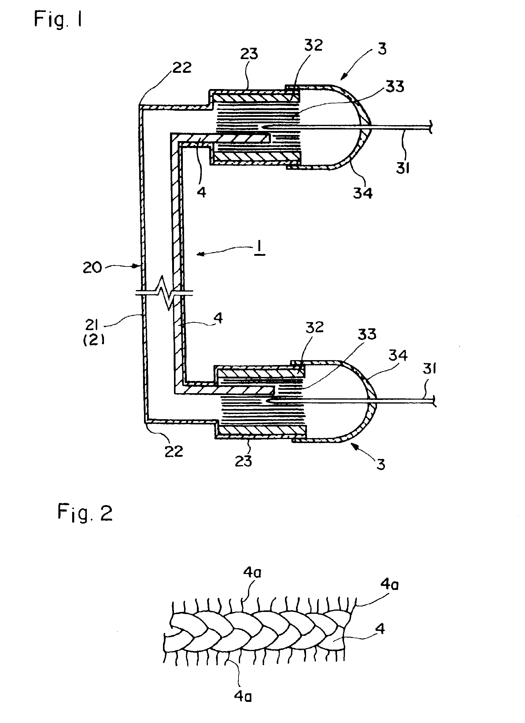
[0174]A U-shaped carbon wire heating element sealing heater (straight portion length: 700 mm) was produced using carbon wires (heating element) having different absorption water quantities and temperature rise test was carried out under a following condition so as to confirm generation of the black spot. In the meantime, upon manufacturing of the heater, pressure inside the quartz glass pipe 20 was 1 torr at a heater temperature of 1200° C.

[0175]Temperature rise condition

[0176]Temperature rise atmosphere: atmosphere open system

[0177]Element temperature:

[0178]Operating time:

Table 1 shows a result of this temperature rise test.

[0179]

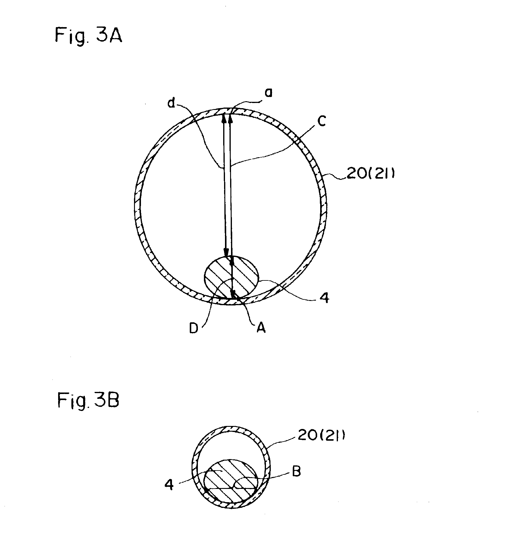
TABLE 1Heater manufacturingconditionAbsorp-Quan-InsideRatio of pipetionQuantitytitydiameter ofinside diameterwaterof pipesof blackquartz glasswhen the wirequantityhaving thespotspipe (mm)diameter is 1(g / cm3)generation(piece)Com-425 ×5 of 5Infiniteparative10−5Infiniteexample 19910 Example 1421 ×0 of 5010−40000

[0180]In the carbon wire heating element sealing...


PUM

PropertyMeasurementUnit
heightaaaaaaaaaa
diameteraaaaaaaaaa
diameteraaaaaaaaaa

Abstract

A carbon wire heating element sealing heater is provided. Therein, a carbon wire heating element using carbon fibers is sealed in a quartz glass member, wherein absorption water quantity of the carbon wire heating element is 2×10⁻³ g / cm3 or less.

Description

BACKGROUND OF THE INVENTION[0001]1. Field of the Invention[0002]The present invention relates to a carbon wire heating object sealing heater and a fluid heating apparatus using the same heater and more particularly to a carbon wire heating object sealing heater having an excellent heating characteristic which allows it to be used preferably for semiconductor processing and a fluid heating apparatus using the same heater.[0003]2. Description of the Related Art[0004]Semiconductor manufacturing processing requires strict temperature control under a heat treatment environment for various kinds of heat treatment processes such as oxidation, diffusion and CVD processing. Further, heating means in the heat treatment process absolutely needs to be non-generation source of a substance which deteriorates semiconductor performance such as impure metal. For the reason, a heater in which the outside of its heating element composed of tungsten and the like is covered with quartz glass has been of...

Claims


Application Information

Patent Timeline
26 Apr 2005
Publication
US6885814B2
IPC
H05B3/14; H01L23/34
CPC
H05B3/145; H01L2924/0002; H01L2924/00; H05B3/44
Inventors
SAITO, TAKANORI; MORI