Method for making a silicon carbide resistor with silicon/silicon carbide contacts by induction heating

Inactive Publication Date: 2005-05-03
REDUNNDANT MATERIALS
View PDF20 Cites 2 Cited by
  • Summary
  • Abstract
  • Description
  • Claims
  • Application Information

AI Technical Summary

Benefits of technology

[0013]The method of the invention, which provides direct heating at the location of attachment between the siliconized silicon carbide article, e.g. contacts, and the silicon carbide article, e.g. recrystallized silicon carbide resistor, permits non-conducting ceramic or quartz furnaces to be used essentially indefinitely since the furnace shell is not heated. This completely avoids the serious problem in known furnaces for making joints between siliconized silicon carbide and recrystallized silicon carbide associated with breakdown of the furnace shell due to required high temperature heating of the shell. Such furnaces were typically tube furnaces requiring a consumable graphite shell in order to withstand the high temperatures required, e.g. in excess of 1800° C. The method of the invention, therefore not only avoids replacement cost of the furnace shell but additionally avoids costly and inefficient down time.
[0014]Because of direct heating of the silicon carbide, in the method of the invention, by electromagnetic wave induction, the relatively costly graphite electrodes associated with furnaces used in the known art for fusing siliconized silicon carbide to recrystallized is also avoided as is the down time associated with their replacement.
[0016]Further, because the method of the invention requires less furnace volume and is much more rapid and efficient than methods of the prior art, a vacuum treatment environment can be efficiently used, as opposed to required larger furnace volumes associated with indirect heating methods. Optionally, inert gas atmospheres can also be used in conjunction with the method of the invention while requiring less inert gas per unit than traditional indirect heating methods for the same reasons previously described. Further, the method of the invention is more energy efficient than known methods for fusing siliconized silicon carbide to recrystallized silicon carbide by more than an order of magnitude, i.e. the method of the invention can take one-tenth the energy of traditional heating methods. In the method of the invention relatively little energy is lost as compared with known indirect heating methods. In the method of the invention, using direct electromagnetic induction heating, little energy is lost by undesirably heating furnace components rather than the article to be treated. In particular, there is little heat lost in electrically non-conductive furnace walls. Radiation loss is greatly reduced since only the part being treated radiates significant heat. Conveyors made of non-conductive materials are not heated and there is therefore little heat storage in components other than the part being treated and the method permits heating of only the portion of the part that needs to be heated. The efficiency in heating the siliconized silicon carbide, e.g. contacts, to fuse them to the silicon carbide, e.g. a resistor, can thus be expected to be an order of magnitude better than known methods.

Problems solved by technology

Such known methods are replete with problems and disadvantages.
Such tube furnaces are typically made of graphite in order to withstand the high temperatures required, e.g. in excess of 1800° C. The graphite tube of the furnace is expensive and is consumed during repeated heating and cooling cycles.
In addition to cost of the graphite tube, replacement causes costly and inefficient down time.
Further, in resistance heated furnaces, relatively costly graphite electrodes must be periodically replaced again resulting in costly down time.
Due to cooling requirements for the shell of the furnaces, the furnaces must be large relative to parts being treated, thus use of a vacuum is impractical and the required volume of inert gas is very large relative to the size of the parts thus adding more inefficiency and cost.
Additionally, such known methods are exceedingly inefficient with respect to required heat energy.
As with most indirect heating methods, energy is lost by undesirably heating furnace components rather than the article to be treated.
In particular, there are heat losses in the furnace wall, loss through radiation, loss through conveyors for parts, atmospheric heat losses and undesirable heat storage.

Method used


Image

  • Method for making a silicon carbide resistor with silicon/silicon carbide contacts by induction heating
  • Method for making a silicon carbide resistor with silicon/silicon carbide contacts by induction heating
  • Method for making a silicon carbide resistor with silicon/silicon carbide contacts by induction heating

Examples


example 1

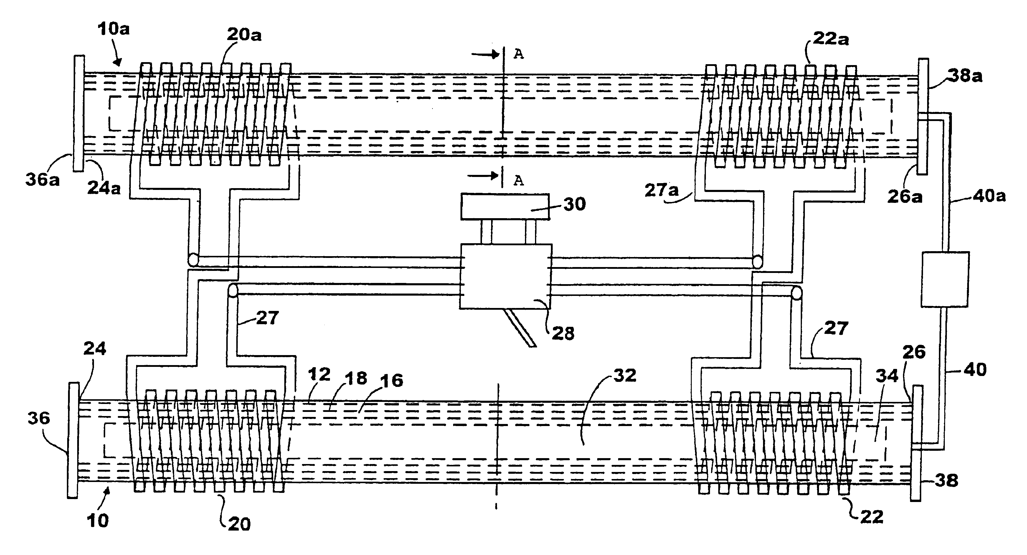
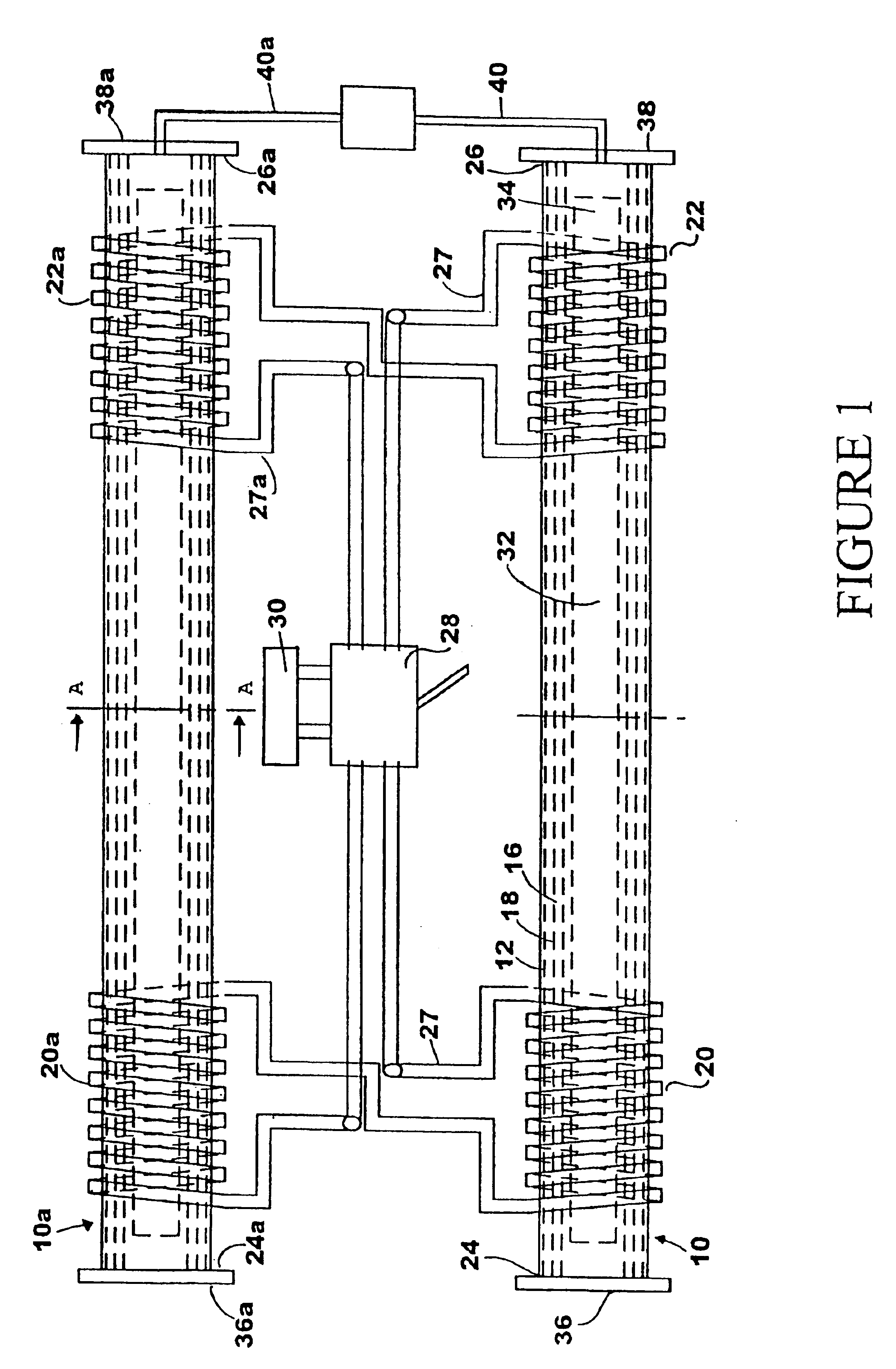
[0033]In a first example, a 25 cm (10 inch) long recrystallized silicon carbide resistors having a outside diameter of about 3.8 cm (1.5 inches) and an inside diameter of about 0.9 cm, each resin bonded to a single siliconized silicon carbide contact having a length of about 20 cm for a total a length of about 45 cm (17⅛ inches), were placed in the above described furnaces so the joint between the resistor and contact was centered in a coil. The vacuum pump was then activated to draw a vacuum in each furnace of less than about 5 Torr. The coils surrounding the joints were than activated for two minutes. All test resistors made under these conditions showed a very good resistor to contact connection and were considered successful with good electrical continuity.

example 2

[0034]Example 1 was repeated except that the resistors had a diameter of about 2 cm and were about 25 cm (10 inches) long. The resin bonded contacts were also about 25 cm (10 inches) long and a contact was used at both ends of the resistor for a total length of about 75 cm (30 inches). Because of the short length, two sets of resistors and contacts could be placed end to end in a single furnace for at total of four units in both furnaces. The coils were adjusted so a joint was located in the center of a coil on each furnace. The vacuum pump was then activated to draw a vacuum of less than about 5 Torr and coils surrounding the centered joints were activated for 3 minutes 10 seconds. Coils were then moved to center two more joints and again activated after reestablishing the vacuum. Unfinished joints continued to be centered within coils and coils activated (four activations total) to finish the resistors with bonded contacts. A longer activation time for the coils than used in examp...

example 3

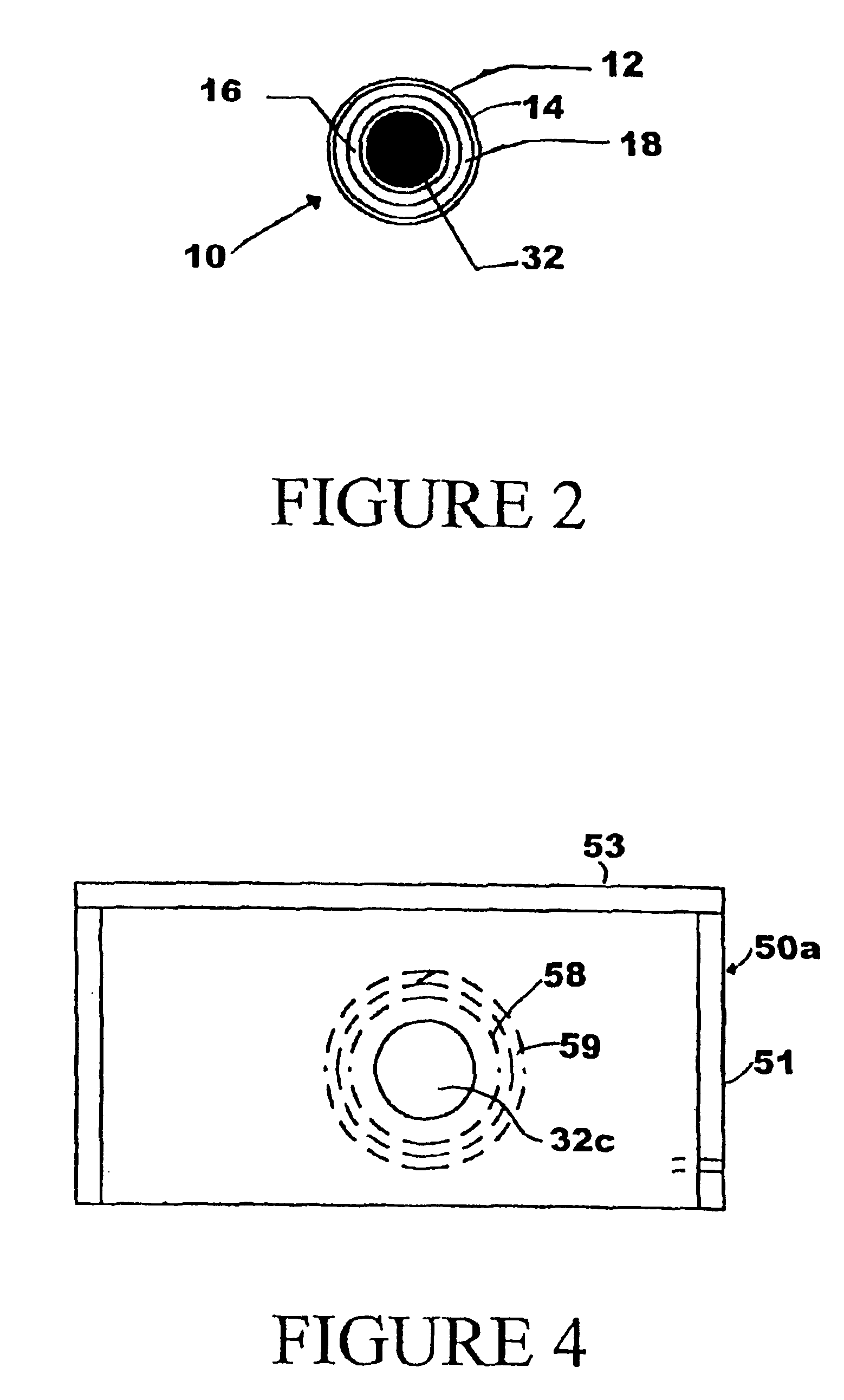
[0035]A furnace different than the furnace of examples 1 and 2 was used so that an inert gas atmosphere could be employed rather than a vacuum. The furnace, as shown in FIG. 3, included two furnace boxes 50 and 50a which had axially aligned holes 52, 54, 52a and 54a to permit a unit including a single resistor 32c with resin bonded contacts 34c and 34d, to pass through the openings so that one contact / resistor joint 56 is in one box 50 and an opposing contact / resistor joint 56a is in the other box 50a. The boxes 50 and 50a were made of electrically non-conducting ceramic fiber board, e.g. calcium silicate fiber board available under the MARINITE trademark. Sides 51, top 53 and partitions 54 were made from the board. Tubular furnace chambers 58 and 58a, made from refractory zirconia, were located inside of each of the furnace boxes 50 and 50a and are supported by walls 57, 59, 57a and 59a, respectively. The tubular furnace chambers were wrapped in an aluminum silicate blanket, e.g. 5...


PUM

PropertyMeasurementUnit
Temperatureaaaaaaaaaa

Abstract

A method for bonding an electrically conductive silicon carbide structure to an electrically conductive siliconized silicon carbide structure by temporarily securing the siliconized silicon carbide structure to the silicon carbide structure; placing the silicon carbide structure with secured siliconized silicon carbide structure into an induction heating furnace having an induction coil which heats electrically conductive material in the furnace when sufficient electrical power at a frequency of from about 300 to about 1000 KC is passed through the coil; and causing sufficient electrical power at a frequency of from about 300 to about 1000 KC to be passed through the coil to raise the temperature of the siliconized silicon carbide structure and silicon carbide structure to a temperature above about 1500° C. at the region of temporary attachment to release the attachment and cause silicon metal to flow from the siliconized silicon carbide structure into the silicon carbide structure to form a siliconized silicon carbide bond between the silicon carbide structure and siliconized silicon carbide structure.

Description

BACKGROUND OF THE INVENTION[0001]This invention relates to heating elements made of silicon carbide and more particularly relates to a method for making a recrystallized silicon carbide resistor having siliconized silicon carbide contacts.[0002]Methods for making recrystallized silicon carbide resistors having siliconized silicon carbide contacts have been previously known. Such methods have involved the fusion of siliconized silicon carbide contacts with a recrystallized silicon carbide resistor by holding the resistor and contacts together, e.g. with a bonding resin, and indirectly heating the combination in a gas or electrical resistance heated furnace, e.g. a tube furnace, to fuse the contacts to the resistor by flow of silicon from the contacts into the resistor.[0003]Such known methods are replete with problems and disadvantages. Such tube furnaces are typically made of graphite in order to withstand the high temperatures required, e.g. in excess of 1800° C. The graphite tube ...

Claims


Application Information

Patent Timeline
IPC IPC(8): C04B35/622C04B35/653C04B37/00H05B6/10
CPCC04B35/565C04B35/653C04B37/001C04B37/008H05B6/105B32B2315/02C04B2235/658C04B2235/6581C04B2235/80C04B2237/365C04B2235/428
Inventor DUNN, MICHAEL P.TIERNEY, BRIAN M.
Owner REDUNNDANT MATERIALS
Why Eureka
Try Eureka