Single module electric power conversion apparatus

a technology of electric power conversion and single module, which is applied in the direction of electrical apparatus construction details, dc-ac conversion without reversal, localised screening, etc., can solve the problems of inability to miniaturize an electric power conversion apparatus, the power supply of an igbt drive and protection circuit cannot be integrated with an intelligent module in a conventional apparatus, etc., to achieve high reliability, reduce weight, and reduce the effect of weigh

Inactive Publication Date: 2005-05-03
MITSUBISHI ELECTRIC CORP
View PDF8 Cites 41 Cited by
  • Summary
  • Abstract
  • Description
  • Claims
  • Application Information

AI Technical Summary

Benefits of technology

[0012]This invention is achieved to solve the above problems, and its object is to provide an electric power conversion apparatus that is miniaturized and reduced in weight by integrating not only an IGBT drive and protection circuit but also a power supply circuit for supplying power into a conventional intelligent module which is an electric power conversion circuit. That is, its object is not only to perform the miniaturization and weight reduction of the inverter apparatus, but also to obtain an electric power conversion apparatus that is highly reliable, sophisticated, and excellent in safety, by mixedly arranging the power supply circuit and other functions in the electric power conversion apparatus, i.e., a conventional intelligent module.
[0014]In addition, another object is to provide an electric power conversion apparatus with not only a conventional IGBT drive and protective function, but also diagnostic functions such as an alarm signal and failure history, and a high value-added function such as trimming adjustment of a semiconductor device protection circuit for electric power conversion by mixedly mounting not only the above-described power supply circuit, but also a digital control circuit using a microcomputer through increasing an electronic component mounting space by implementing the multilayer structure and double-sided mounting of a board in the electric power conversion apparatus.

Problems solved by technology

Usually, they are contained in separate cases respectively due to problems of heat generation and switching noise of the semiconductor device for electric power conversion.
However, a power supply 122 supplying power to an IGBT drive and protection circuit board is also contained in a case different from these due to problems of heat generation and noise.
Nevertheless, since the current capacity of the power supply circuit itself also becomes large in that with large power capacity, the power supply circuit is contained in a case different from an intelligent module due to a cooling method of suppressing heat generation of a power transformer etc., and a problem of a board mounting space.
On the other hand, since only one side of the board becomes the mounting space of electronic components, this becomes a struggle of raising a degree of integration and functions of the IGBT drive and protection circuit.
As described above, a power supply of an IGBT drive and protection circuit cannot be integrated with an intelligent module in a conventional apparatus due to problems of heat generation and switching noise of a semiconductor device, and a board mounting space.
Hence, there is a disadvantage that it is not possible to miniaturize an electric power conversion apparatus, and in extension, an inverter apparatus itself.

Method used


Image

  • Single module electric power conversion apparatus
  • Single module electric power conversion apparatus
  • Single module electric power conversion apparatus

Examples


embodiment 1

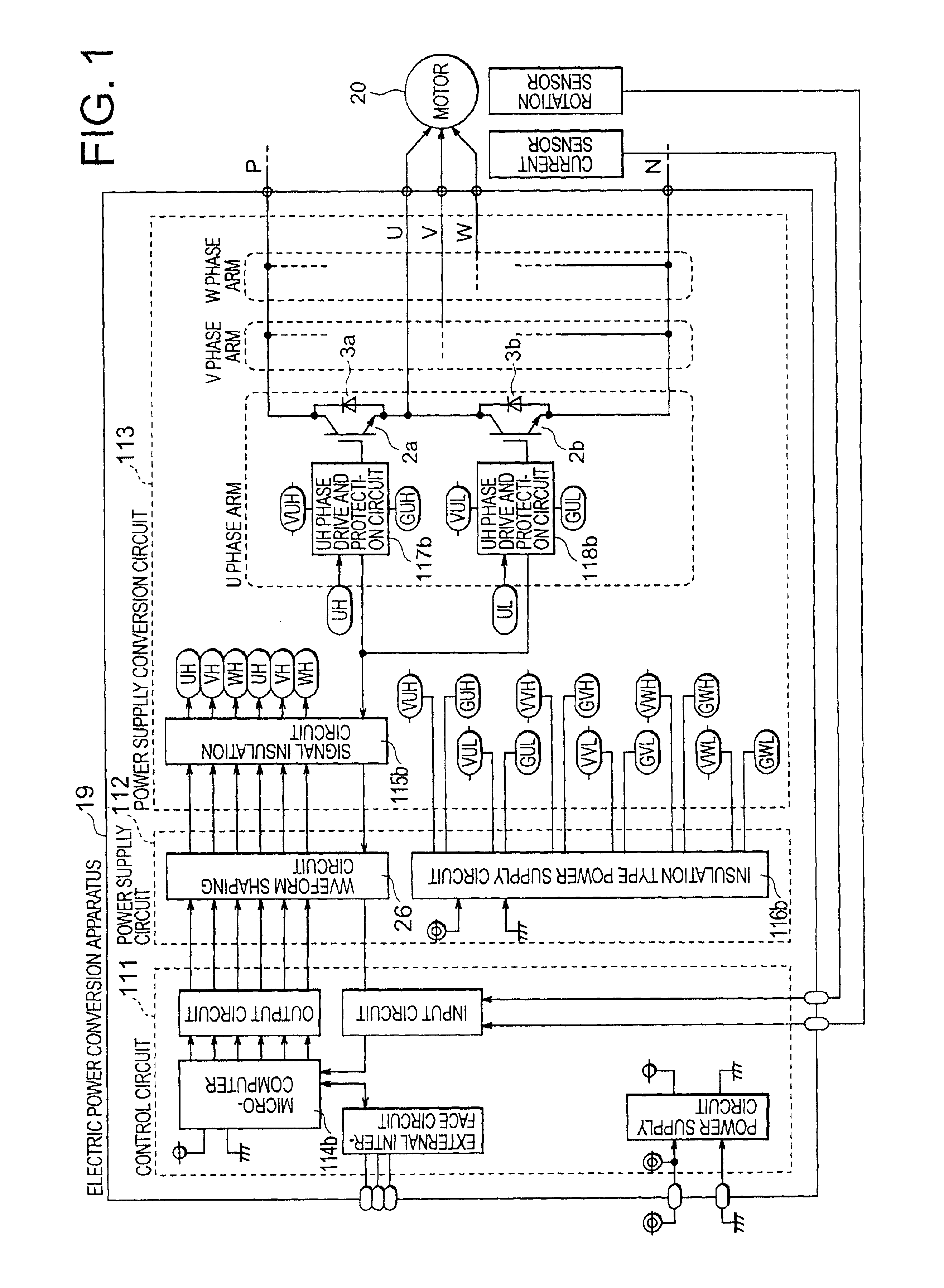
[0049]FIG. 1 is a block diagram showing a circuit configuration of an electric power conversion apparatus according to a first embodiment of the present invention.

[0050]In FIG. 1, reference numeral 19 denoted an electric power conversion apparatus, reference numeral 20 denotes a three phase motor, reference numeral 111 denotes a control circuit including a microcomputer 114b etc., reference numeral 112 denotes a power supply circuit which includes a waveform shaping circuit 26 and an insulation type power supply circuit 116b, and supplies power to an IGBT drive and protection circuit board, and reference numeral 113 denotes an electric power conversion circuit including a signal insulation circuit 115b and a U phase arm which typically indicates only one phase of three phases. In addition, the U phase arm includes a UH phase drive and protection circuit 117b and a UL phase drive and protection circuit 118b as drive and protection means, and switching devices 2a and 2b and the free w...

embodiment 2

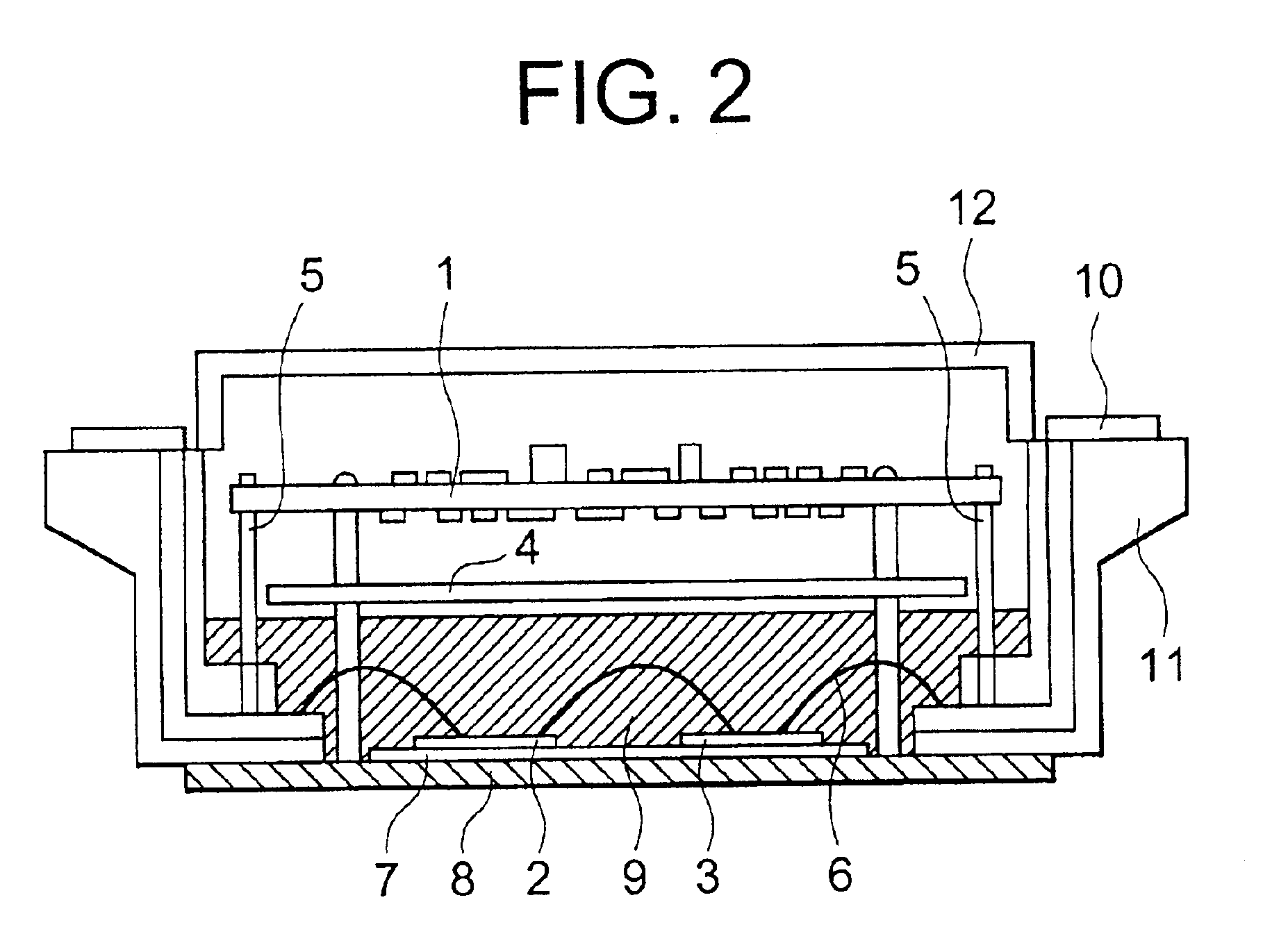
[0056]FIG. 3 is a sectional view showing an internal configuration of an electric power conversion apparatus according to a second embodiment of this invention.

[0057]In addition to the configuration of the above-described first embodiment, for example as shown in FIG. 3, this embodiment is to together fasten the PCB1 and metal shielding plate 4 with using each screw 13a for fixing the PCB1 to the switching power module case 11, and to obtain electric connection with the metal shielding plate 4 and base plate 8 through each insert nut 14 molded with the switching power module case 11 in one piece.

[0058]That is, in order to secure a parts mounting space in the board, the board, i.e., PCB 1, where the circuit that drives and protects the semiconductor devices for electric power conversion, and the power supply circuit are mixedly mounted, is made to be a double-sided one. Hence, in order to obtain noise reduction effectiveness equal to or better than a fully-grounded pattern on the bac...

embodiment 3

[0060]In this embodiment, in addition to the above-described second embodiment, the PCB 1 is made to be substantially multilayer, and a fully-grounded pattern on an internal layer is connected with the base plate 8 electrically and thermally through the metal shielding plate 4 and the insert nut 14.

[0061]Thus, in this embodiment, a heavily heating component is made to radiate heat to the base plate 8 connected to an external cooler through an inner layer pattern and the metal shielding plate 4 by making a board, where a circuit which drives and protects semiconductor devices for electric power conversion, and a power supply circuit are mixedly mounted, be a multilayer board, connecting the inner layer pattern of the board to a lead portion of the heavily heating component, and together fastening the metal shielding plate 4 with the board through the inner layer pattern at multiple points. Hence, it is possible to improve the cooling effect of the PCB 1 and to suppress temperature ri...


PUM


Abstract

To perform a miniaturization and weight reduction of an electric power conversion apparatus, and in extension, the miniaturization of an inverter apparatus itself. In the inverter apparatus which converts a DC voltage into an AC voltage, a semiconductor device for electric power conversion, and a drive and protection circuit which drives and protects this semiconductor device for electric power conversion, and a power supply circuit which supplies power to this drive and protection circuit are integrated in the same module.

Description

[0001]This application is based on Application No. 2001-315113, filed in Japan on Oct. 12, 2001, the contents of which are hereby incorporated by reference.BACKGROUND OF THE INVENTION[0002]1. Field of the Invention[0003]This invention relates to an electric power conversion apparatus used for an electric vehicle driving apparatus or an inverter apparatus, and in particular, to structure for miniaturization and weight reduction, and advanced functionality of drive and protection means of a semiconductor device for electric power conversion, failure diagnosis, or the like.[0004]2. Description of the Related Art[0005]In the electric vehicle, in particular, an electric motorcar, or a hybrid car, the miniaturization and weight reduction of an inverter apparatus for three-phase motor drive are required for a mounting space and fuel cost reduction. Generally, an inverter apparatus consists of an electric power conversion apparatus for converting a DC voltage into an AC voltage, and a contr...

Claims


Application Information

Patent Timeline
Patent Type & Authority Patents(United States)
IPC IPC(8): H02P29/02H05K7/14H02M1/08H02M7/00H02M7/48
CPCH02M1/08H02M1/32H05K9/002H05K7/1432H02M7/003H01L2224/48091H01L2224/48137H01L2924/181H01L2924/13055H01L2924/13091H05K7/14322H01L2924/00014H01L2924/00012H01L2924/00
Inventor MAEKAWA, HIROTOSHIMATSUOKA, SYOUGO
Owner MITSUBISHI ELECTRIC CORP
Why Eureka
Try Eureka