
Flow rate measurement for industrial sensing applications using unsteady pressures

a flow rate measurement and industrial sensing technology, applied in the direction of volume/mass flow measurement, measurement devices, instruments, etc., can solve the problems of electromagnetic flowmeters being prone to problems, electrical wiring and power that requires enormous cost, and safety issues and sometimes miles of wires

Inactive Publication Date: 2005-05-10
EXPRO METERS
View PDF4 Cites 157 Cited by
  • Summary
  • Abstract
  • Description
  • Claims
  • Application Information

AI Technical Summary

Benefits of technology

"The present invention provides a system for measuring the flow rate of fluid in pipes in industrial processes without the need for a flow restriction or change in flow velocity. The system uses filters to measure the vortical pressure field at two different locations in the pipe, and a signal processor calculates the cross-correlation between these two signals to determine the convection velocity of the fluid. This velocity is then used to determine the flow rate of the fluid. The system can measure the velocity of any inhomogeneous flow field, such as gas bubbles or particles, and can be used in any environment or application. The system has no flow range limitations and can measure very low flow rates or maximum flow rates. It can also be combined with a controller and used in an industrial process control system."

Problems solved by technology

Often, these field applications are subject to harsh and varying environmental conditions that provide challenges for designers of such sensors.
However, such a technique requires a change in the flow properties (e.g., flow velocity or density) at the two measurement points to make the measurement.
The flowmeters of the prior art require electrical wiring and power that requires enormous cost, safety issues and sometimes miles of wires.
Also, prior art flowmeters such as vortex, turbine and venturi types use obstructions in the flow path that disrupt the flow to varying degrees.
In addition sediment, gumming, plugging, corrosion, and erosion of certain features of the sensing region of the meter can affect the accuracy of the flowmeter.
In particular, electromagnetic flowmeters are prone to problems caused by poor process grounding, and specialized sleeves that prone to damage.
Process noise is a problem and can be caused by slurries, high consistency pulp stock, or upstream chemical additions.
Such process noise can lead to inaccurate flow measurement in these types of prior art flowmeters.
The accuracy and sensitivity can be affected by the length of cabling for remote transmitters and can be adversely influenced by proximity to other electrical devices Another flow meter of the prior art includes a friction flowmeter such as that set forth in U.S. Pat. No. 6,253,624, titled “Friction Flowmeter” wherein a transducer determines the pressure drop of a fluid flowing along a pipe.
In addition, with certain applications the surface of the pipe, and the friction factor thereby, would change over time and decrease the accuracy of the meter in predicting fluid flow rates.
Typical electronic, or other, transducers of the prior art often cannot be placed in industrial process environments due to sensitivity to electromagnetic interference, radiation, heat, corrosion, fire, explosion or other environmental factors.

Method used


Image

  • Flow rate measurement for industrial sensing applications using unsteady pressures
  • Flow rate measurement for industrial sensing applications using unsteady pressures
  • Flow rate measurement for industrial sensing applications using unsteady pressures

Examples


Embodiment Construction

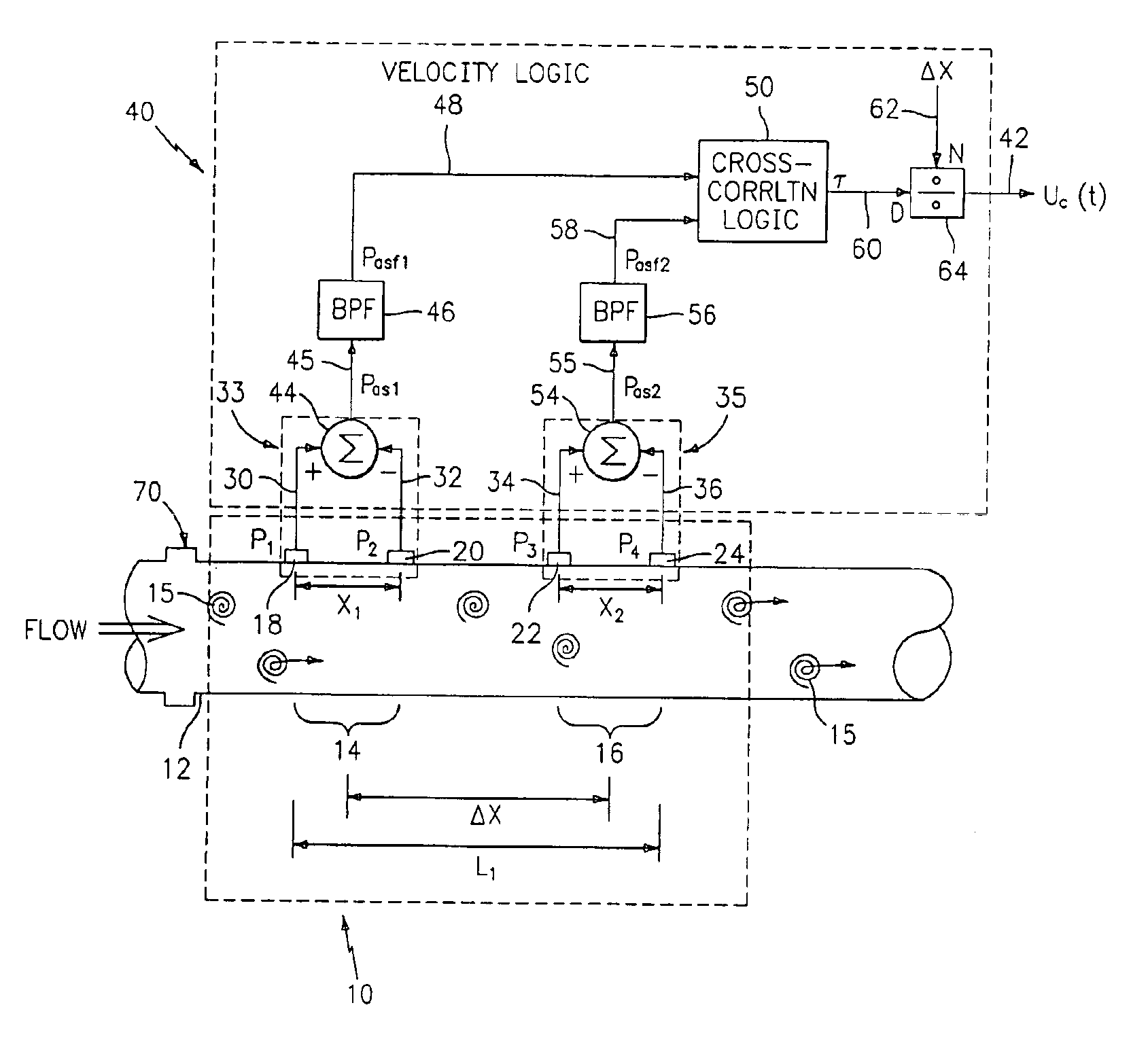
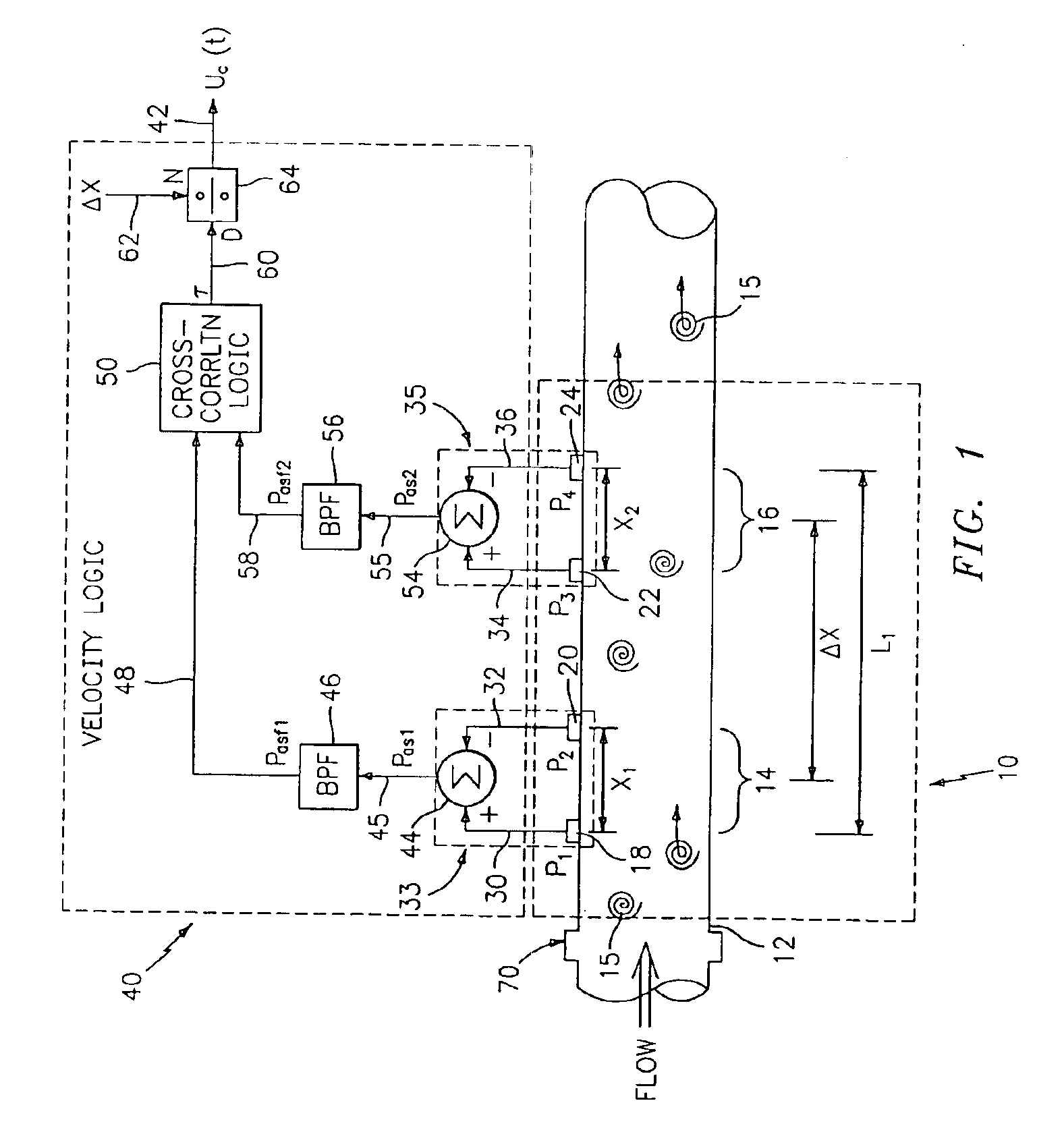
[0054]Referring to FIG. 1, a velocity and flow measurement system includes a sensing section 10 along a pipe 12 and a velocity logic section 40. The pipe (or conduit) 12 has two measurement regions 14,16 located a distance ΔX apart along the pipe 12. At the first measurement region 14 are two unsteady (or dynamic or ac) pressure sensors 18,20, located a distance X1 apart, capable of measuring the unsteady pressure in the pipe 12, and at the second measurement region 16, are two other unsteady pressure sensors 22,24, located a distance X2 apart, capable of measuring the unsteady pressure in the pipe 12. Each pair of pressure sensors 18,20 and 22,24 act as spatial filters to remove certain acoustic signals from the unsteady pressure signals, and the distances X1,X2 are determined by the desired filtering characteristic for each spatial filter, as discussed hereinafter. The flow measurement system 10 of the present invention measures velocities associated with unsteady flow fields and / ...


PUM


Abstract

Flow rate measurement system includes two measurement regions 14,16 located an average axial distance ΔX apart along the pipe 12, the first measurement region 14 having two unsteady pressure sensors 18,20, located a distance X1 apart, and the second measurement region 16, having two other unsteady pressure sensors 22,24, located a distance X2 apart, each capable of measuring the unsteady pressure in the pipe 12. Signals from each pair of pressure sensors 18,20 and 22,24 are differenced by summers 44,54, respectively, to form spatial wavelength filters 33,35, respectively. Each spatial filter 33,35 filters out acoustic pressure disturbances Pacoustic and other long wavelength pressure disturbances in the pipe 12 and passes short-wavelength low-frequency vortical pressure disturbances Pvortical associated with the vortical flow field 15. The spatial filters 33,35 provide signals Pas1,Pas2 to band pass filters 46,56 that filter out high frequency signals. The Pvortical -dominated filtered signals Pasf1,Pasf2 from the two regions 14,16 are cross-correlated by Cross-Correlation Logic 50 to determine a time delay τ between the two sensing locations 14,16 which is divided into the distance ΔX to obtain a convection velocity Uc(t) that is related to an average flow rate of the fluid (i.e., one or more liquids and / or gases) flowing in the pipe 12. The invention may also be configured to detect the velocity of any desired inhomogeneous pressure field in the flow. The invention may also be combined with an instrument, an opto-electronic converter and a controller in an industrial process control system.

Description

CROSS REFERENCES TO RELATED APPLICATIONS[0001]This application is an continuation-in-part of commonly owned U.S. patent applications, Ser. No., 09 / 346,607, entitled “Flow Rate Measurement Using Unsteady Pressures”, filed Jul. 2, 1999 now abandoned.TECHNICAL FIELD[0002]This invention relates to the measurement of flow rate of a fluid and more particularly to measuring flow rate using unsteady pressure measurements for use in industrial sensing applications.Background Art[0003]An industrial process sensor is typically a transducer that responds to a measurand with a sensing element and converts the variable to a standardized transmission signal, e.g., an electrical or optical signal, that is a function of the measurand. Industrial process sensors utilize transducers that include flow measurements of an industrial process such as that derived from slurries, liquids, vapors and gasses in refinery, chemical, paper, pulp, petroleum, gas, pharmaceutical, food, mining, minerals and other fl...

Claims


Application Information

Patent Timeline
Patent Type & Authority Patents(United States)
IPC IPC(8): G01F1/74G01F1/712G01F1/704G01F1/708G01F1/7086
CPCG01F1/7086G01F1/74G01F1/712
Inventor GYSLING, DANIEL L.BRYANT, REBECCA M.WINSTON, CHARLES R.
Owner EXPRO METERS
Learn More