Aperture fluorescent lamp, surface illuminator, manufacturing methods thereof, liquid crystal display device, and electronic device

a technology of fluorescent lamps and manufacturing methods, applied in the manufacture of electrode systems, electric discharge tubes/lamps, and applications of luminescent coatings, etc., can solve the problems of difficult to manufacture aperture fluorescent lamps having the long glass tube length, difficult to manufacture small-diameter aperture fluorescent lamps having an inner diameter of 3 mm or less, and difficulty in thinning, etc., to achieve easy and accurate manufacturing, low cost, and high reliability

Inactive Publication Date: 2005-05-10
VISTA PEAK VENTURES LLC
View PDF30 Cites 11 Cited by
  • Summary
  • Abstract
  • Description
  • Claims
  • Application Information

AI Technical Summary

Benefits of technology

[0030]In view of the above, it is an object of the present invention to provide an aperture fluorescent lamp manufacturing method capable of easily manufacturing even a relatively small-diameter aperture fluorescent lamp with high yield and at low cost.
[0031]It is another object of the present invention to provide a small-diameter aperture fluorescent lamp, a thin, narrow-frame, and lightweight surface illuminator, a liquid crystal display device having the surface illuminator, and an electronic device having the liquid crystal display device at low costs.
[0032]It is still another object of the present invention to provide a surface illuminator manufacturing method capable of accurately and easily positioning an aperture portion, improving yield, and contributing to thinning, narrow frame formation, weight reduction, and achievement of low cost.

Problems solved by technology

Consequently, it is practically difficult to manufacture a small-diameter aperture fluorescent lamp having an inner diameter of 3 mm or less.
Consequently, it is also difficult to manufacture an aperture fluorescent lamp having the long glass tube length.
It can therefore be understood that there are difficulties of thinning, narrow frame formation, and weight reduction for the backlight using the aperture fluorescent lamp manufactured by the described manufacturing method.
Thus, there are also difficulties of thinning, narrow frame formation, and weight reduction for both of a liquid crystal display device using the backlight and an electronic device using such the liquid crystal display device.
Thus, much time, and labor must be expended, thereby causing an increase in cost.
Therefore, there are problems of high costs for the backlight 115 as a surface illuminator using the aperture fluorescent lamp 107 manufactured by the described manufacturing method, a liquid crystal display device using the backlight 115, and a device using such the liquid crystal display device.
Thus, material and process costs are increased by attaching (adhering) of the positioning pieces 108, and there are difficulties of thinning, narrow frame formation, and weight reduction when the aperture fluorescent lamp 107 is incorporated in the backlight 115.
Since a member around the aperture fluorescent lamp 107 becomes to be a visual obstacle during orientation alignment, the aperture portion 106 cannot be correctly positioned, thus deteriorating yield.
Consequently, luminance uniformity is deteriorated.
The above problem occurs even when a general lamp other than the aperture fluorescent lamp is used.

Method used


Image

  • Aperture fluorescent lamp, surface illuminator, manufacturing methods thereof, liquid crystal display device, and electronic device
  • Aperture fluorescent lamp, surface illuminator, manufacturing methods thereof, liquid crystal display device, and electronic device
  • Aperture fluorescent lamp, surface illuminator, manufacturing methods thereof, liquid crystal display device, and electronic device

Examples


first embodiment

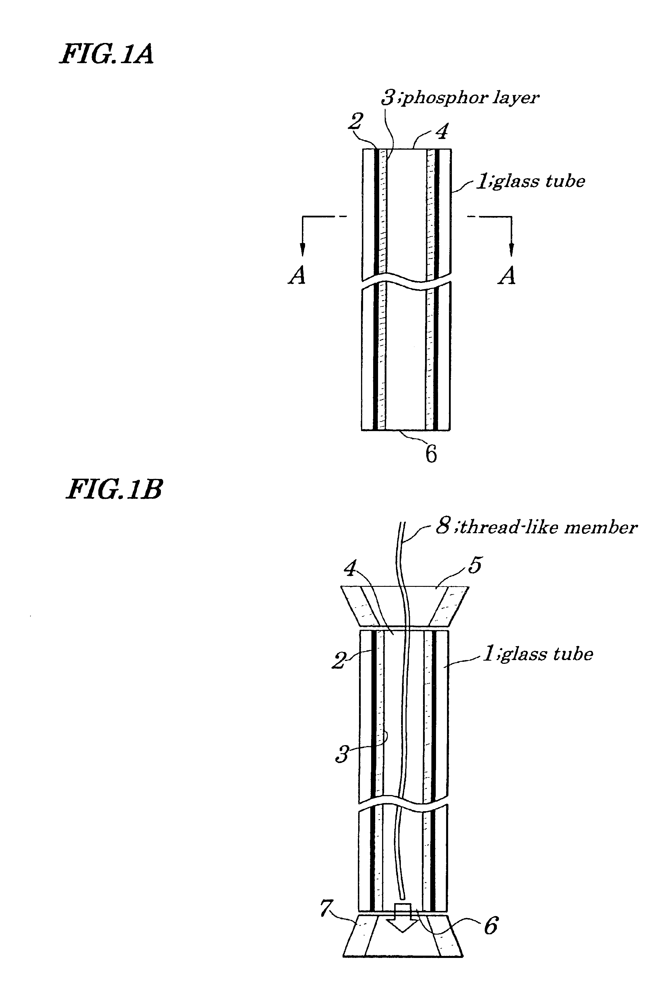
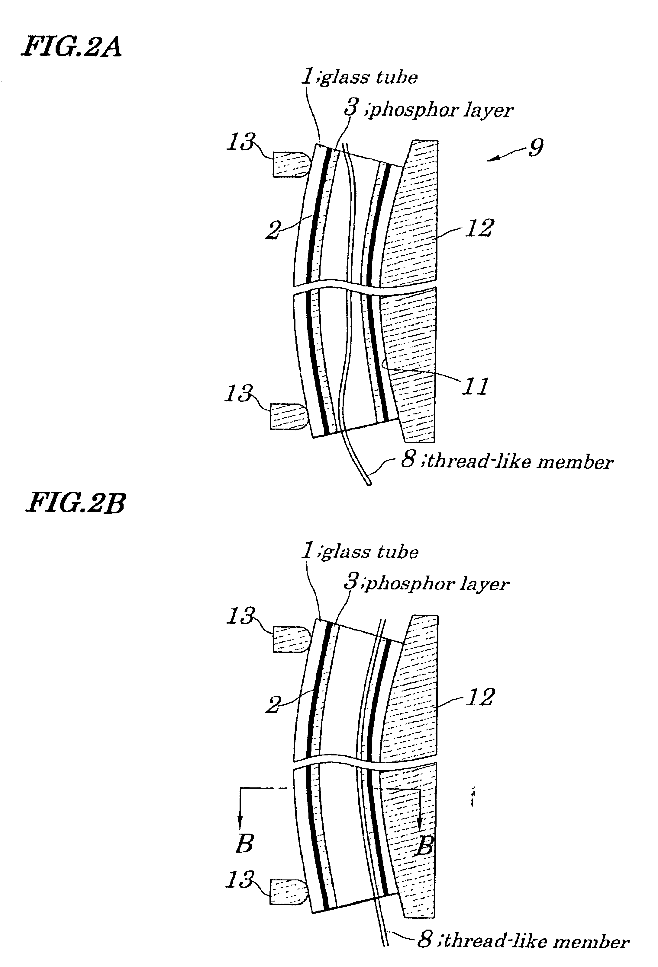
[0125]FIGS. 1A, 1B, 2A and 2B are process views illustrating an aperture fluorescent lamp manufacturing method according to a first embodiment of the present invention. FIGS. 3A and 3B are views illustrating the aperture fluorescent lamp manufacturing method of the first embodiment. Specifically, FIG. 3A is a sectional view taken along line A—A of FIG. 1A and FIG. 3B is a sectional view taken along line B—B of FIG. 2B. FIG. 4 is a view illustrating the aperture fluorescent lamp manufacturing method of the first embodiment; and FIG. 5 is a sectional view showing a constitution of the aperture fluorescent lamp. FIG. 6 is another sectional view showing the constitution of the aperture fluorescent lamp; and FIG. 7 is a partially expanded perspective view showing a constitution of a lead conductor of the aperture fluorescent lamp. FIG. 8 is a characteristic view showing a relation (directional characteristic) between a radiation direction and luminance of the aperture fluorescent lamp. F...

second embodiment

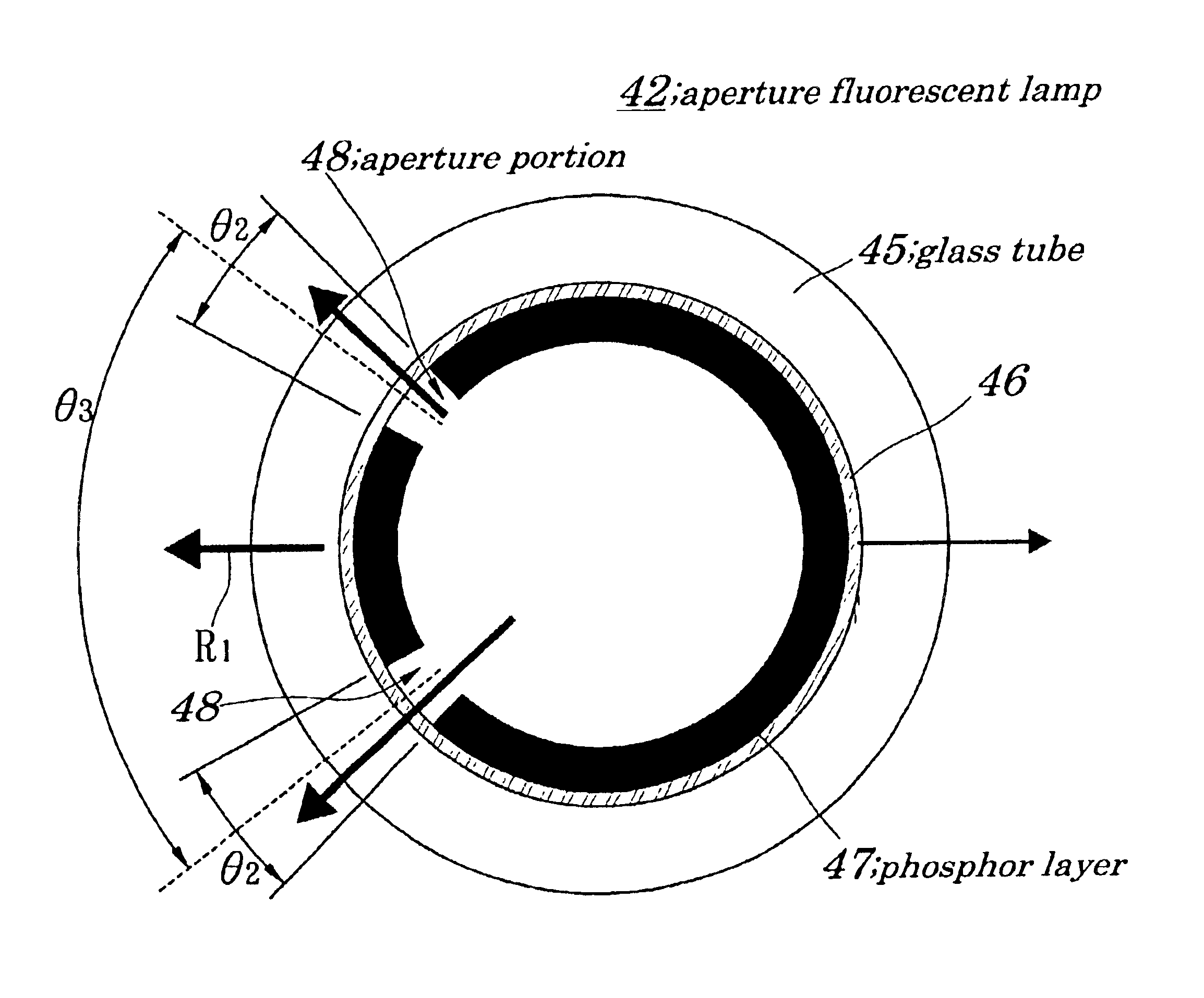
[0166]FIGS. 16A and 16B are views illustrating operation or constitution of a backlight according to a second embodiment of the invention. Specifically, FIG. 16A is a characteristic view showing a relation (luminance distribution characteristic) between a position of a light emission surface of the backlight in a vertical axis direction and luminance above the backlight, and FIG. 16B is a sectional view showing the constitution of the backlight. FIG. 17 is a sectional view illustrating a constitution of an aperture fluorescent lamp of the embodiment; and FIG. 18 a characteristic view showing a relation (directional characteristic) between a radiation direction and luminance of the aperture fluorescent lamp.

[0167]The backlight of the second embodiment is different from the backlight of the first embodiment in the following respects. That is, while the aperture fluorescent lamp having an aperture portion provided in one place is used in the first embodiment, in the second embodiment, ...


PUM

PropertyMeasurementUnit
angle gapaaaaaaaaaa
opening angleaaaaaaaaaa
inner diameteraaaaaaaaaa

Abstract

A relatively small-diameter aperture fluorescent lamp is manufactured easily with high yield and at low cost. An aperture portion is formed in a manner that a thread-like member is inserted into a glass tube having an ultraviolet ray reflection layer and a phosphor layer formed on its inner surface, the glass tube is bent in a predetermined shape by using a bending jig, the thread-like member is pressed to the phosphor layer formed in a predetermined region in the bending member side of the glass tube while both ends thereof are pulled tight, the thread-like member is reciprocated, and phosphor of the phosphor layer in this region is exfoliated.

Description

[0001]The present Application is a Divisional Application of U.S. patent application Ser. No. 09 / 902,710, filed on Jul. 12, 2001 now U.S. Pat No. 6,533,633.BACKGROUND OF THE INVENTION[0002]1. Field of the Invention[0003]The present invention relates to an aperture fluorescent lamp manufacturing method, which is suitably used for manufacturing a relatively small-diameter aperture fluorescent lamp having an aperture portion opened for light projection in a part of a straight glass tube in the axial direction, a manufacturing method of a surface illuminator provided with an aperture fluorescent lamp, a relatively small-diameter aperture fluorescent lamp, a surface illuminator provided with an aperture fluorescent lamp, a liquid crystal display device provided with the surface illuminator, and an electronic device provided with the liquid crystal display device.[0004]The present application claims priority of Japanese Patent Application No.2000-215239 filed on Jul. 14, 2000, which is he...

Claims


Application Information

Patent Timeline
Patent Type & Authority Patents(United States)
IPC IPC(8): H01J61/00H01J61/72H01J9/20G02F1/1335F21V8/00F21Y103/00G02F1/13357H01J9/22H01J9/28H01J61/42
CPCH01J61/72H01J9/20G02F1/1335
Inventor ONO, SHIN-ICHIROU
Owner VISTA PEAK VENTURES LLC
Why Eureka
Try Eureka