
Electrosurgical apparatus

Inactive Publication Date: 2005-05-10
XO CARE
View PDF8 Cites 71 Cited by
  • Summary
  • Abstract
  • Description
  • Claims
  • Application Information

AI Technical Summary

Benefits of technology

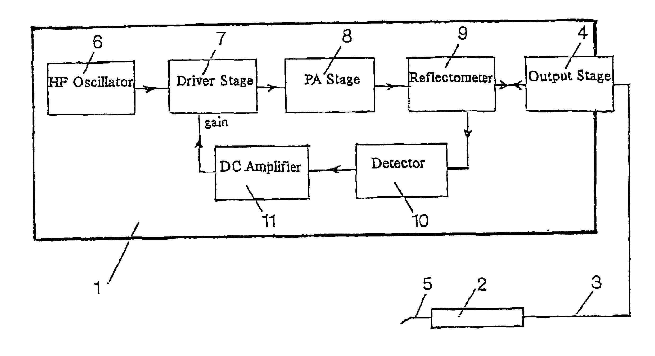
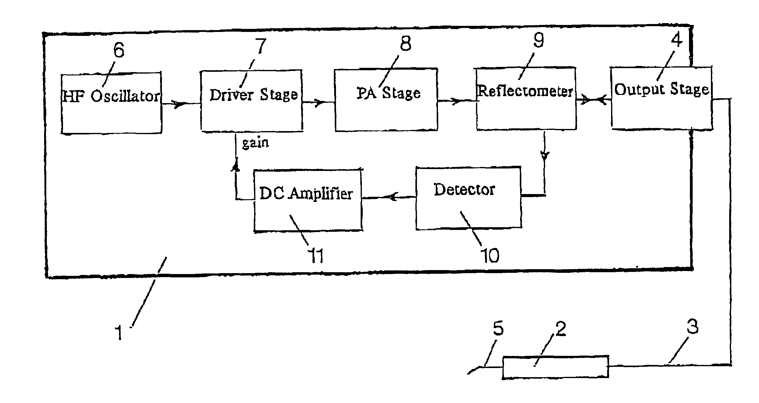
[0021]Concurrently herewith the apparatus of the invention is performing a continuous and automatic adjustment of the output power level, in as much as the gain of the driver stage automatically can be controlled to decrease, when the reflectometer is sensing that a major part of the output signal is being reflected—that is to say during incisions with small depths (low load). Hereby the sparkling can be controlled and efficiently prevented.

Problems solved by technology

At the same time the output power may at no instant be larger than necessary, because too large power delivery will result a.o. in unclean cuts and possibly also in sparkling between electrode and tissue which causes tissue necrosis and thereby complicates and prolonges the healing proces.
Otherwise, the result would be very painful damages such as periostitis, bone necrosis and sequestration of bone tissue.
As already mentioned a very rapid reduction of the power supplied by the electrode must take place in such instances, because, otherwise, the result could be very painful damages to bone tissue or tooth substances.
If on the other hand the cutting depth of the electrode is suddenly decreased, then there will also be a sudden decrease in the load or susceptance due to the decreasing area of contact between tissue and electrode.
Again it is very important that the power from the electrode is decreased very rapidly, because otherwise the result could be sparkling and serious burning and destruction of tissue.
However, in the electosurgical apparatus just described it has been seen that the regulation range for output power is not sufficiently broad to range—without further measures—all the way from cutting in the tissue surface without sparkling (minimum load) and up to cutting in full depth with maximum power (maximum load).

Method used


Image

  • Electrosurgical apparatus
  • Electrosurgical apparatus

Examples


Embodiment Construction

[0026]The generator part 1 is based on a BP-oscillator 6 which preferably is a crystal controlled, 50 watt generator with an output frequency of 27.125 Mhz which is within a free transmission frequency range.

[0027]The oscillator 6 supplies a driver stage 7 which preferably is a 5 watt amplifier stage, and in the embodiment shown the driver signal is conducted to a PA-stage 8. In a preferred embodiment the PA-stage 8 includes a transformer which is phase splitting the driver sign by 180 degrees, and the resulting signal drives a following PA-stage, whereafter the power is combined in a following transformer.

[0028]The PA-stage 8 is followed by a directional coupler or a reflectometer 9 which is in communication with the output stage 4 which preferably includes a low-pass filter for reduction of the radiation of harmonics before the output signal is conducted to an output terminal.

[0029]The handpiece 2 includes means for replacably coupling of an electrode 5 which usually is a thin wir...


PUM


Abstract

An electrosurgical apparatus comprises a high frequency generator (1) with an associated power control system, a handpiece (2) with means for removably mounting an electrode (5) therein, and a connection cable (3) between an output (4) of the generator and the handpiece. The transfer characteristic of the system provides a substantially true ohmic transfer of loads on the electrode side of the connection cable (3) to the generator side thereof at or around a predetermined load on the electrode.In order to achieve a fully automatic and optimalized control af power supplied from a cutting electrode, whereby the control is instantly responding, to changes in the electrode load, the electrosurgical apparatus is characterized in that the power control system comprises a driver stage (7) followed by a reflectormeter (9) adapted and arranged to sense the generator output (4). A detector (10) supplies a detector signal which represents the reflected signal on the output (4), and the detector signal is communicated to the driver stage (7) for controlling the gain thereof.

Description

BACKGROUND OF THE INVENTION[0001]1. Technical Field of the Invention[0002]The present invention relates to an electrosurgical apparatus of the type which is used, in particular by surgeons and dentists, to perform incisions and also to stop bleeding.[0003]2. Prior Art[0004]Electrosurgical equipment of the type in question is based on a power generator which supplies a high frequency alternating current. Via a connection cable this current is conducted to an electrode—the so-called active electrode—which is replacably mounted in a handpiece. For dissections the active electrode is usually made of thin metal wire which remains cold because of good conductivity, but when the electrode is advanced through tissue, a local heating is generated in the tissue a. o. because of the electrical resistance of the tissue.[0005]This heating causes a molecular dissolution of the tissue cells since the generated heat causes both intra- and extracellular generation of steam which bursts the tissue ce...

Claims


Application Information

Patent Timeline
IPC IPC(8): A61B18/12A61B18/14
CPCA61B18/1206A61B2018/00875A61B2018/00785A61B2018/00702
Inventor KRISTENSEN, TOM
Owner XO CARE
Learn More