
Method of depositing metal film and metal deposition cluster tool including supercritical drying/cleaning module

a metal film and metal deposition technology, applied in the field of metal film deposition, can solve the problems of temperature-induced damage of the substrate, especially detrimental corner clipping, plasma damage of the surface of the substrate,

Inactive Publication Date: 2005-05-10
TOKYO ELECTRON LTD
View PDF290 Cites 49 Cited by
  • Summary
  • Abstract
  • Description
  • Claims
  • Application Information

AI Technical Summary

Benefits of technology

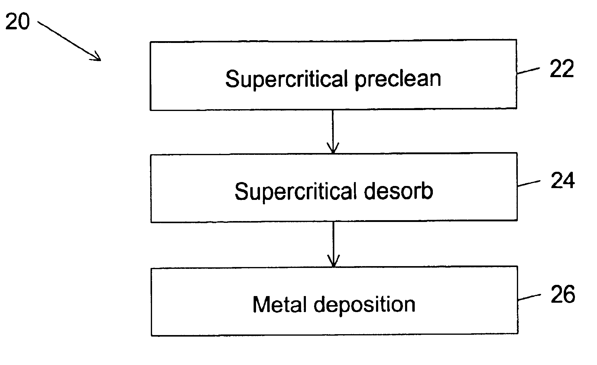
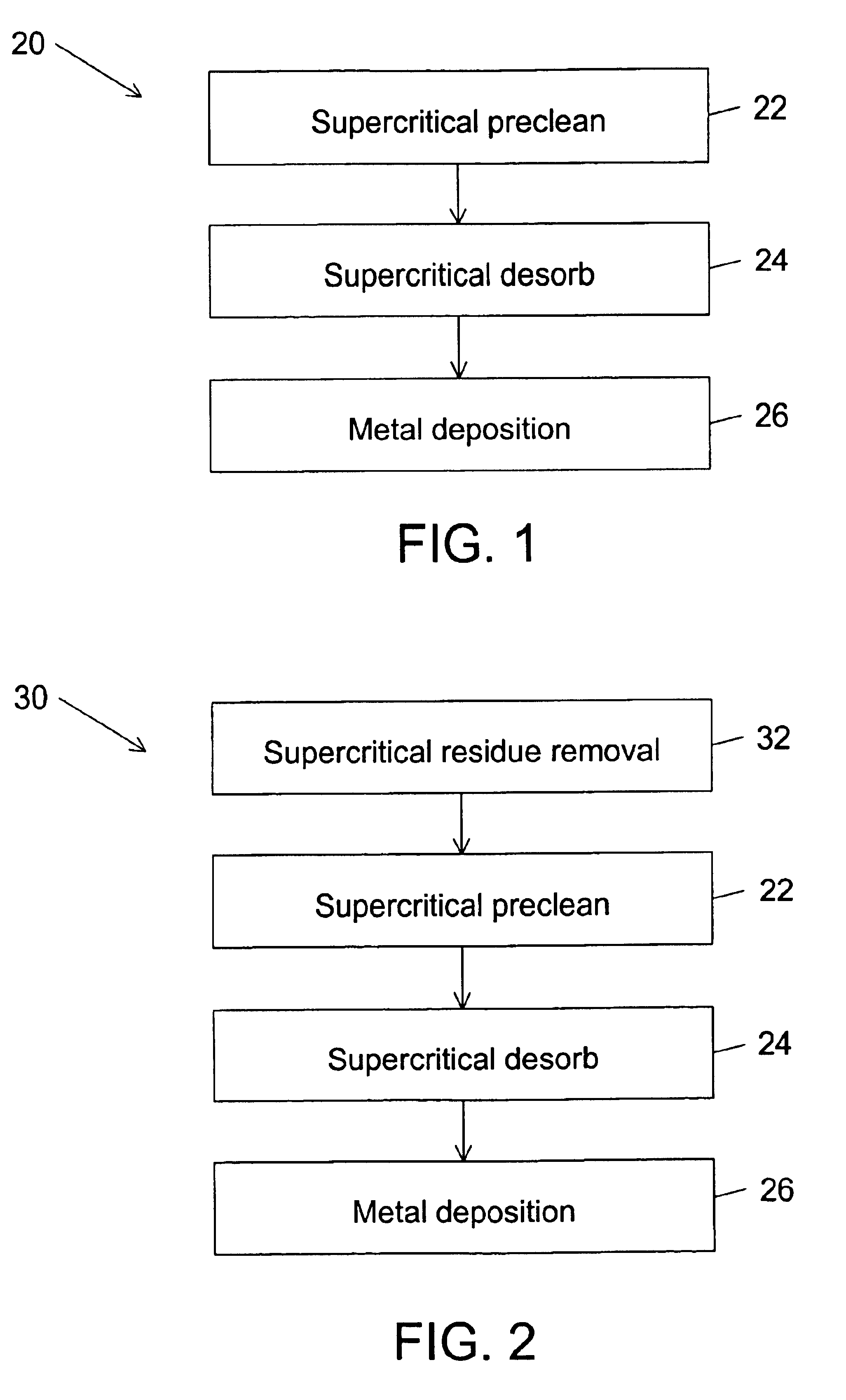
[0020]A method of depositing a metal film on a substrate includes a supercritical preclean step, a supercritical desorb step, and a metal deposition step. Preferably, the preclean step comprises maintaining supercritical carbon dioxide and a chelating agent in contact with the substrate in order to remove an oxide layer from a metal surface of the substrate. More preferably, the preclean step comprises maintaining the supercritical carbon dioxide, the chelating agent, and an acid in contact with the substrate where the acid dissolves the oxide layer while the chelating agent attaches to loose metal ions and carries away the loose metal ions. Alternatively, the preclean step comprises maintaining the supercritical carbon dioxide and an amine in contact with the oxide layer where the amine dissolves the oxide layer and carries away metal ions. The desorb step comprises maintaining supercritical carbon dioxide in contact with the substrate in order to remove adsorbed material from the substrate. The metal deposition step then deposits the metal film on the substrate without exposing the substrate to an oxidizing material which oxidizes the metal surface of the precleaned substrate and without exposing the substrate to a nonvolatile adsorbing material which adsorbs to the substrate.

Problems solved by technology

Because the desorb step of the prior art operates at elevated temperatures, there is potential for temperature induced damage of the substrate.
In the preclean step, the plasma can cause plasma damage of the surface of the substrate.
The corner clipping is especially detrimental to smaller dimension integrated circuits since the corner clipping reduces separation of adjacent lines leading to unacceptable electrical interference between the adjacent lines.
Not only does the sputter-etch preclean cause physical damage of integrated circuits, it could also causes electrical damage.
Further, sputtering of the underlying metal layer in the trenches and the via holes can cause barreling as well as causing deposition of sputtered material on sidewalls of the trenches and the via holes.
Moreover, the sputter-etch preclean is inappropriate for precleaning polymer based materials due to expected damage caused by the physical bombardment in the sputter-etch preclean.
Also, even if the sputter-etch preclean can be used, the hydrogen ions cannot be used when the polymer materials are exposed since the hydrogen will hydrate the polymer-based materials.
Additionally, the sputter-etch preclean becomes less effective as an aspect ratio (depth divided by width) of the trenches and of the via holes increases.
Both the degas module and the sputter-etch module require high vacuum pumps and associated vacuum plumbing, which increases purchase and maintenance costs of the cluster tool.
The sputter-etch module further increases the purchase and maintenance costs of the cluster tool because it relatively complex and requires frequent maintenance to ensure that it does not become a source of particulate contamination.

Method used


Image

  • Method of depositing metal film and metal deposition cluster tool including supercritical drying/cleaning module
  • Method of depositing metal film and metal deposition cluster tool including supercritical drying/cleaning module
  • Method of depositing metal film and metal deposition cluster tool including supercritical drying/cleaning module

Examples


Embodiment Construction

[0025]The preferred method of the present invention is schematically illustrated in FIG. 1. The preferred method 20 deposits a metal film on a substrate. Preferably, the substrate is a semiconductor substrate having via holes through a dielectric material to an underlying metal layer. When the metal film is deposited on the semiconductor substrate, the metal film contacts the underlying metal layer at the via holes. More preferably, the semiconductor substrate includes via holes and trenches in a dual damascene structure. In the dual damascene structure, the metal layer also contacts the underlying metal layer at the via holes. Alternatively, the metal film is deposited on an alternative substrate where the metal film contacts an exposed metal surface on the alternative substrate.

[0026]The preferred method 20 comprises a supercritical preclean step 22, a supercritical desorb step 24, and a metal deposition step 26. In the supercritical preclean step 22, the substrate is maintained i...


PUM

PropertyMeasurementUnit
temperaturesaaaaaaaaaa
temperatureaaaaaaaaaa

Abstract

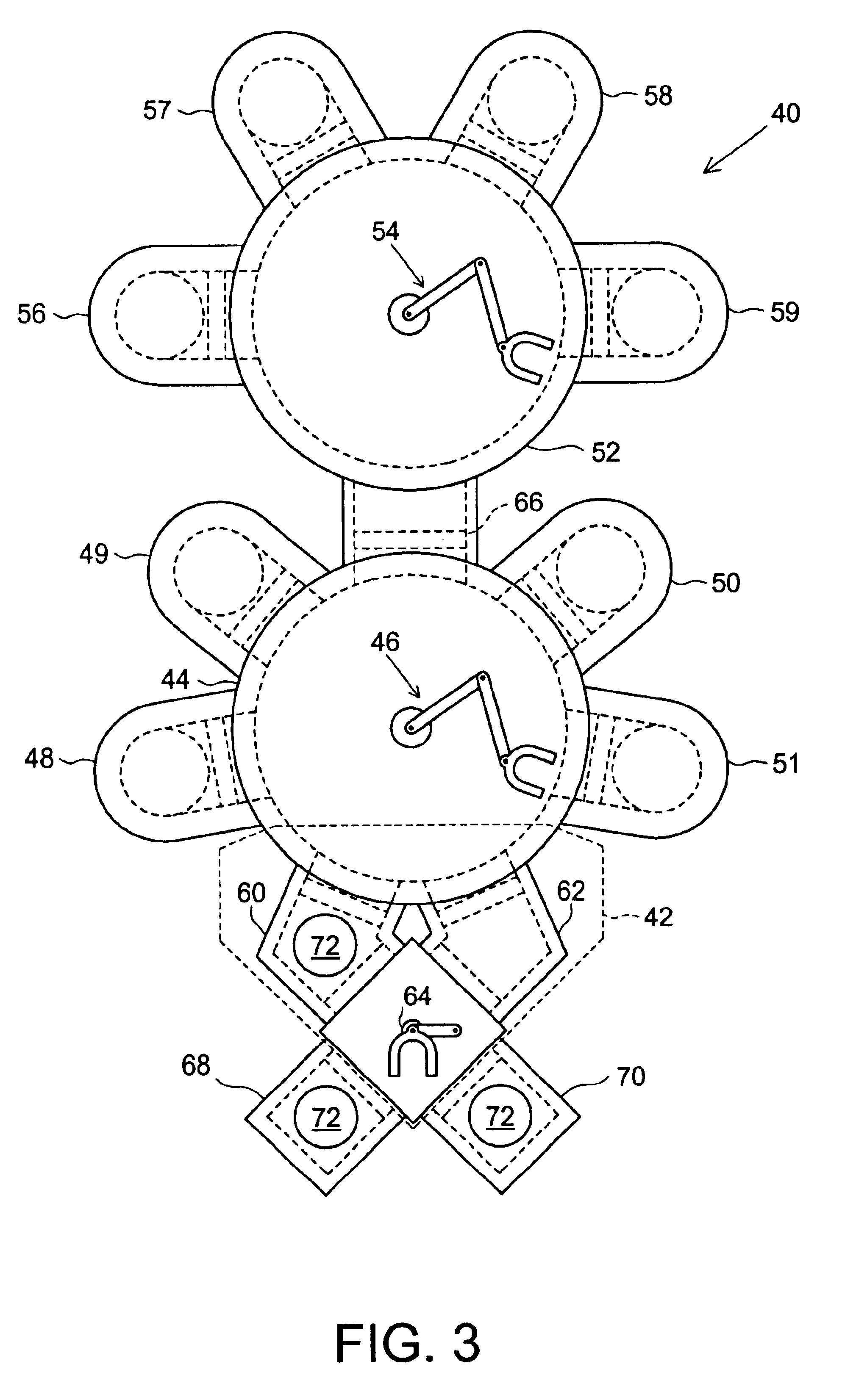
A method of depositing a metal film on a substrate includes a supercritical preclean step, a supercritical desorb step, and a metal deposition step. Preferably, the preclean step includes maintaining supercritical carbon dioxide and a chelating agent in contact with the substrate in order to remove an oxide layer from a metal surface of the substrate. More preferably, the preclean step includes maintaining the supercritical carbon dioxide, the chelating agent, and an acid in contact with the substrate. Alternatively, the preclean step includes maintaining the supercritical carbon dioxide and an amine in contact with the oxide layer. The desorb step includes maintaining supercritical carbon dioxide in contact with the substrate in order to remove adsorbed material from the substrate. The metal deposition step then deposits the metal film on the substrate without exposing the substrate to an oxidizing material which oxidizes the metal surface of the precleaned substrate and without exposing the substrate to a nonvolatile adsorbing material which adsorbs to the substrate. An apparatus for depositing the metal film on a substrate includes a transfer module, a supercritical processing module, a vacuum module, and a metal deposition module. The supercritical processing module is coupled to the transfer module. The vacuum module couples the metal deposition module to the transfer module. In operation, the apparatus for depositing the metal film performs the supercritical preclean step, the supercritical desorb step, and the metal deposition step.

Description

RELATED APPLICATIONS[0001]This application claims priority from U.S. Provisional Patent Application No. 60 / 199,580 filed on Apr. 25, 2000, which is incorporated by reference.FIELD OF THE INVENTION[0002]This invention relates to the field of deposition of film. More particularly, this invention relates to the field of deposition of films onto a substrate where a prior processing step includes desorbing or precleaning of the substrate.BACKGROUND OF THE INVENTION[0003]Deposition of a metal film in semiconductor processing often requires desorb and preclean steps prior to the deposition of the metal film. The desorb and preclean steps assure good adhesion of the metal film to a substrate and also provides better contact resistance between a substrate metal and the metal film.[0004]In the prior art, the desorb step, the preclean step, and the deposition of the metal film take place within a cluster tool so that the substrate is not exposed to atmosphere between the desorb or preclean ste...

Claims


Application Information

Patent Timeline
Patent Type & Authority Patents(United States)
IPC IPC(8): C23C14/02C23C16/02H01L21/00H01L21/70H01L21/768H01L21/285H01L21/02H01L21/28H01L21/027H01L21/304H01L21/308
CPCC23C14/021C23C16/0227H01L21/02063H01L21/02101H01L21/67167H01L21/67184H01L21/67207H01L21/76814H01L21/67028H01L21/28556Y10S438/906H01L21/28
Inventor BIBERGER, MAXIMILIAN A.SCHILLING, PAUL E.
Owner TOKYO ELECTRON LTD
Learn More