Low injection charge pump
- Summary
- Abstract
- Description
- Claims
- Application Information
AI Technical Summary
Benefits of technology
Problems solved by technology
Method used
Image
Examples
Embodiment Construction
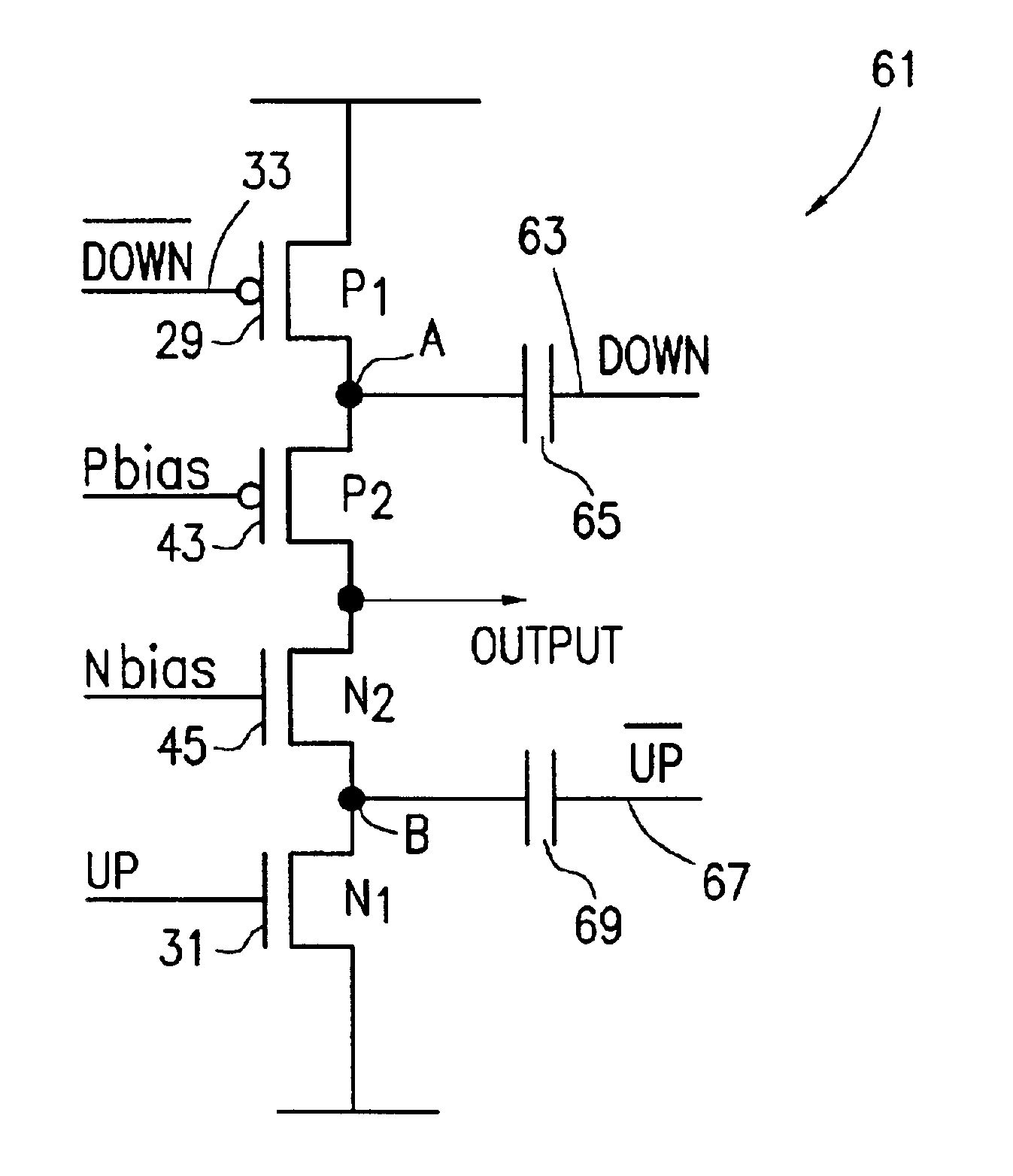
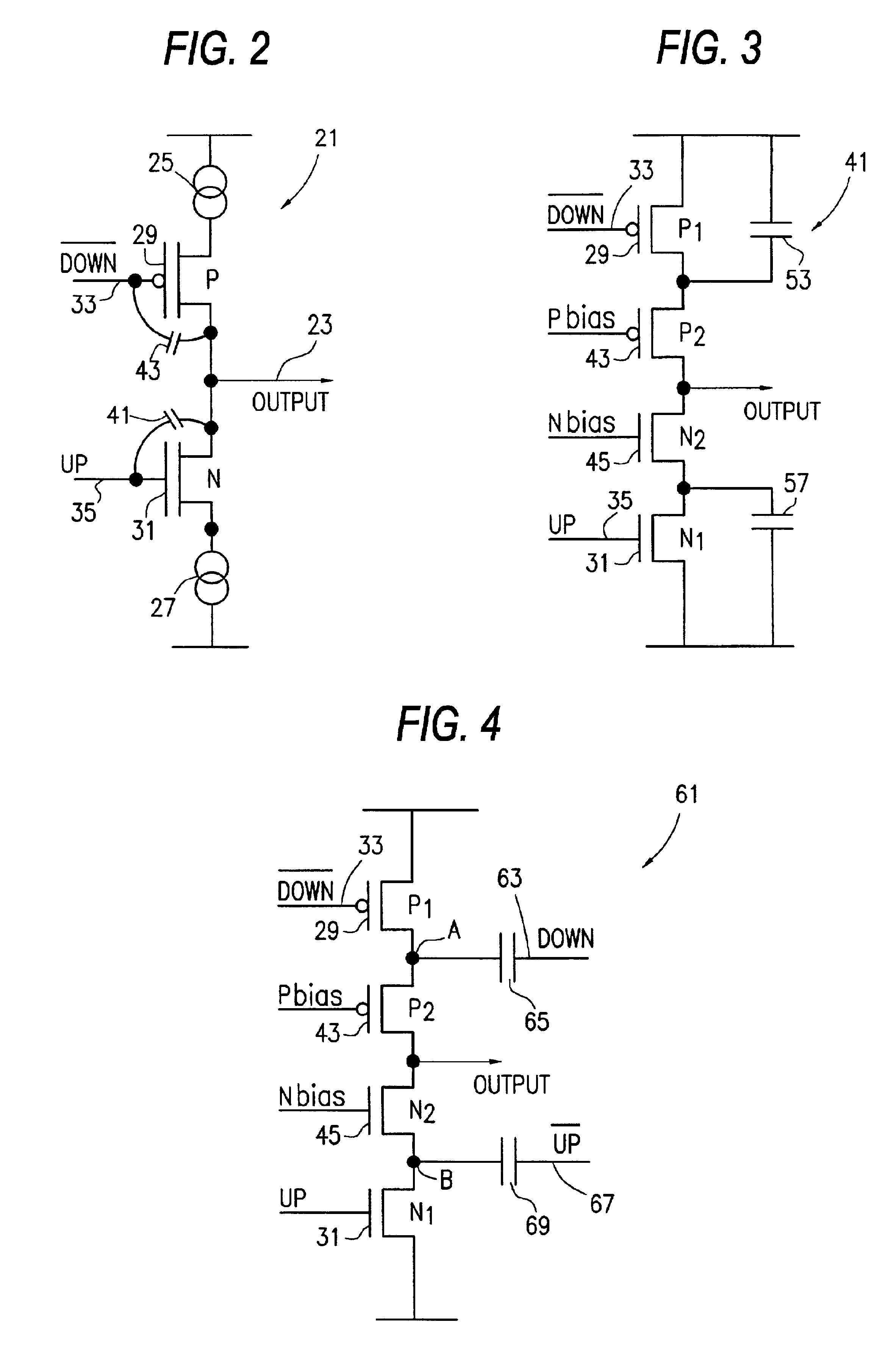
[0019]FIG. 4 illustrates an exemplary embodiment of a CMOS charge pump 61 in accordance with the invention. The circuit is essentially the same as that illustrated in FIG. 3, except for the addition of coupling capacitors 65 and 69 which respectively receive an inverted form of the {overscore (DOWN)} signal applied to gate 33, that is a DOWN signal, and capacitor 69 which receives an inverted form of the UP signal, that is an {overscore (UP)} signal.
[0020]The signal DOWN is applied through capacitor 65 to the common node A of respective switching and D.C. biasing transistors 29 and 43, while the switching signal {overscore (UP)} is applied through capacitor 69 to the common node B between respective transistors 45 and 31. The provision of the switching signals DOWN and {overscore (UP)} to respective nodes A and B provides a fast turn on and turn off of the transistors 29 and 31 without waveform distortion in the resulting output signal. The voltage on the capacitors 65 and 69 settle...
PUM
 Abstract
Description
Claims
Application Information
 - R&D
- Intellectual Property
- Life Sciences
- Materials
- Tech Scout
- Unparalleled Data Quality
- Higher Quality Content
- 60% Fewer Hallucinations
Browse by: Latest US Patents, China's latest patents, Technical Efficacy Thesaurus, Application Domain, Technology Topic, Popular Technical Reports.
© 2025 PatSnap. All rights reserved.Legal|Privacy policy|Modern Slavery Act Transparency Statement|Sitemap|About US| Contact US: help@patsnap.com


