Method and system of automatic delay detection and receiver adjustment for synchronous bus interface

a technology of automatic delay detection and receiver adjustment, applied in the direction of synchronisation signal speed/phase control, generating/distributing signals, instruments, etc., can solve the problems of tightening the physical design requirement of the interface, complicating the system design, and synchronous bus transactions become much more difficult, so as to achieve the best bandwidth possible, improve the tolerance of bus bit misalignment, and improve the effect of bandwidth

Inactive Publication Date: 2005-05-10
MEDIATEK INC
View PDF8 Cites 30 Cited by
  • Summary
  • Abstract
  • Description
  • Claims
  • Application Information

AI Technical Summary

Benefits of technology

[0007]A system implemented with this method is capable of determining whether the sender to receiver delay of every signal (or data) bit is more than the projected capture cycle time (not necessarily one cycle) during a detection and calibration period and to store this delay information in the receiver circuitry. Then the receivers are individually adjusted to receive signals at the appropriate cycle time based on the delay information. Therefore, a synchronous interface implemented with this invention will be able to transfer data with a minimum number of cycles across the interface that is optimized based on the delay limit of that particular bus

Problems solved by technology

However, in high frequency synchronous systems wherein the worst-case delay is more than one cycle and the delay differences among the bits/lines of the bus are more than the cycle time, synchronous bus transactions become much more difficult.
This approach tightens the interface physical design requirement and complicates the system design

Method used


Image

  • Method and system of automatic delay detection and receiver adjustment for synchronous bus interface
  • Method and system of automatic delay detection and receiver adjustment for synchronous bus interface
  • Method and system of automatic delay detection and receiver adjustment for synchronous bus interface

Examples


Embodiment Construction

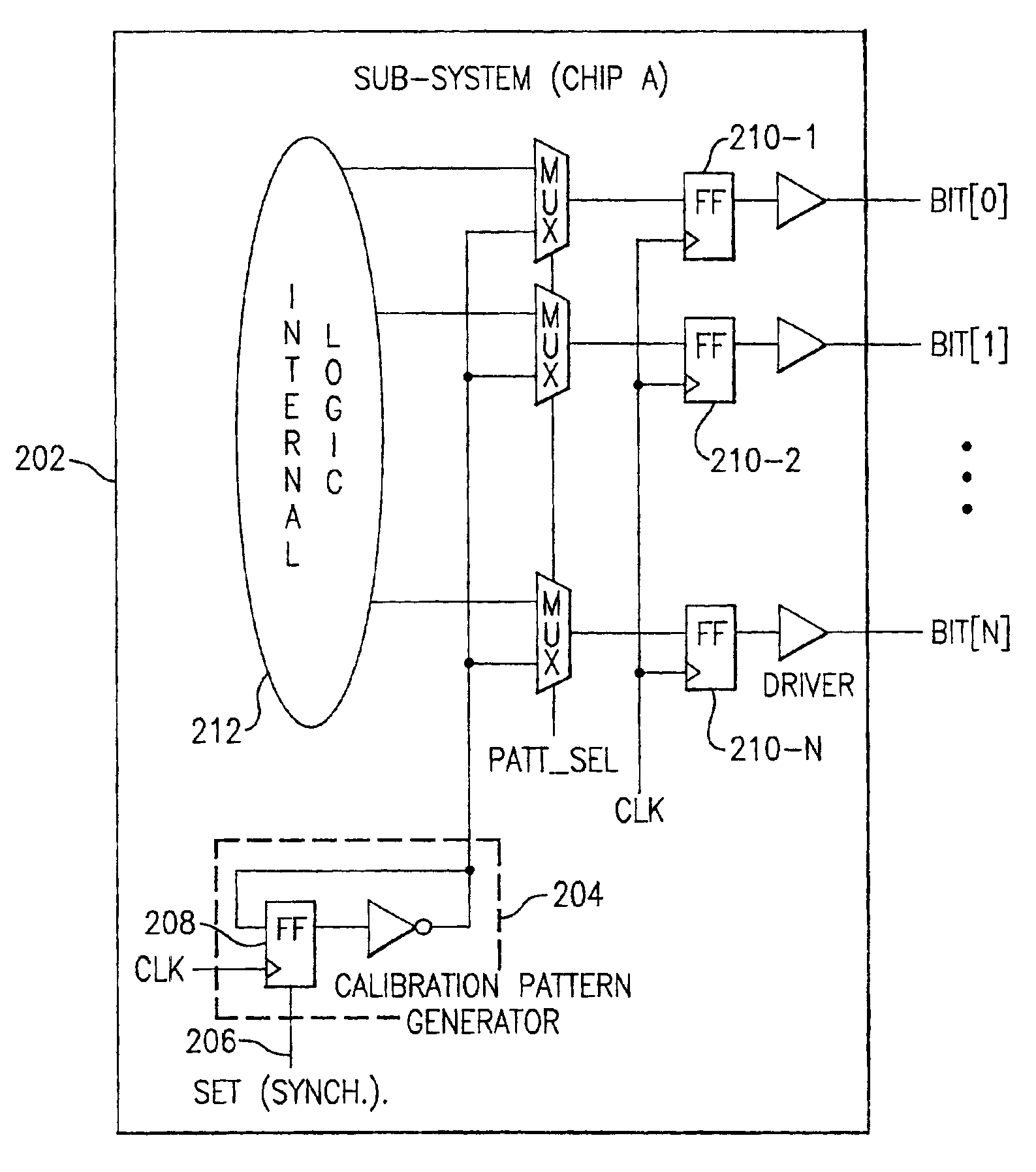
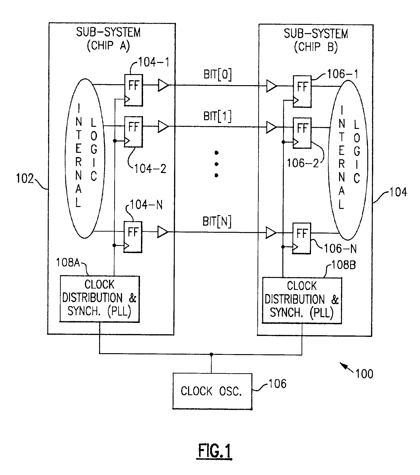
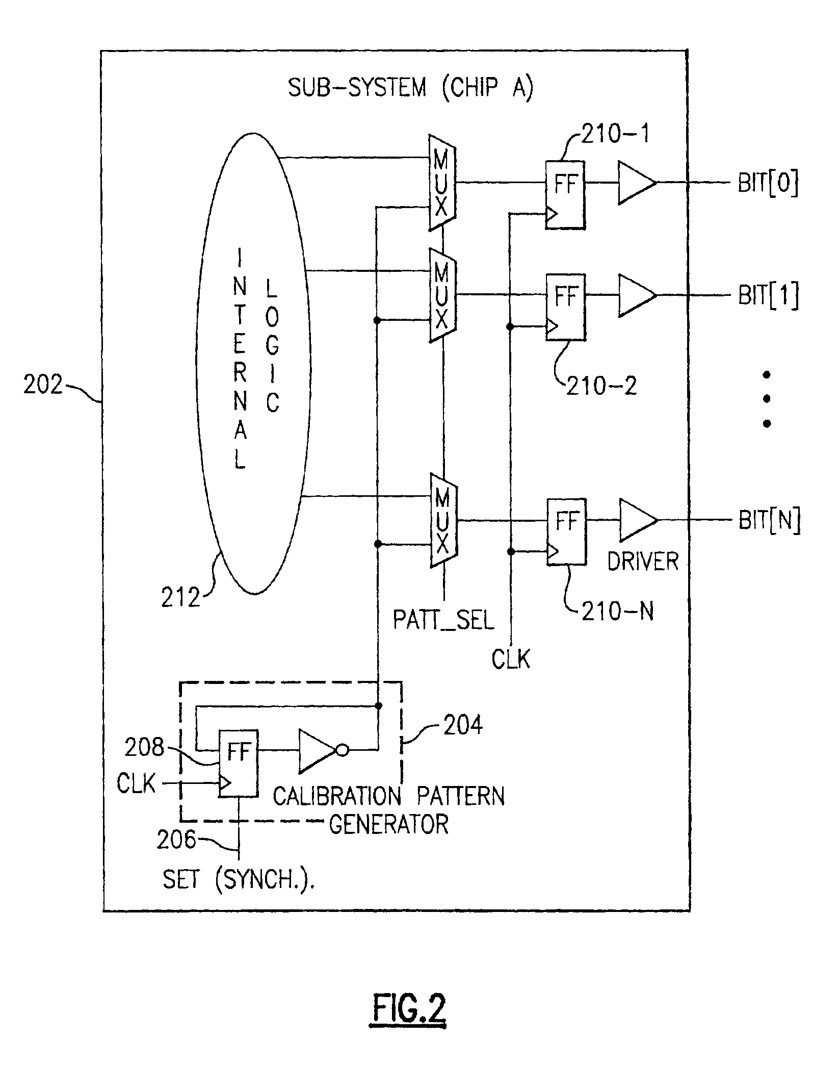
[0016]In a digital system with synchronous bus interface 100 as shown by FIG. 1, the sender subsystem 102 includes one or more integrated circuit chips, such as Chip A, and the receiver subsystem 104, including one or more chips, such as Chip B, maintain clock synchronization by a common clock reference 106. This common clock source 106 is usually provided by a clock / crystal oscillator circuitry or chip. Both subsystems 102 and 104 minimize clock skew through some clock distribution techniques and in most cases with phase-locked loops (PLL) 108A and 108B in high frequency systems. FIG. 1 shows Chip A 102 as the sender and Chip B 104 as the receiver. However, in a bi-directional bus interface, a subsystem, such as Chip A or Chip B in FIG. 1, is a sender and a receiver. FIG. 1 illustrates a unidirectional N-bit bus interface in which the sender flip-flops (FF) 104-I through 104-N, or master-slave latch pairs in a level-sensitive scan design (LSSD), in Chip A 102 transfer signals to th...


PUM


Abstract

An automatic delay detection and receiver adjustment method for a synchronous communications bus system sends a test pattern to the receivers of the system during a detection phase, uses the test pattern to determine a longest delay time for each bus lone, and adjusts a receiver for each bit line to receive incoming signals at a time based on the determined longest delay time.

Description

FIELD OF THE INVENTION[0001]The present invention relates generally to synchronous bus transactions in digital systems, and more particularly to such systems in which the delays of the interface are greater than the system cycle time.BACKGROUND OF THE INVENTION[0002]In a synchronous digital system, especially in a computer system, synchronous buses are preferred and commonly used in between subsystems as interface buses (usually chip-to-chip interfaces) to achieve the high bandwidths required for those systems. For synchronous bus transactions to function properly, both sender (multiple bits of binary lines) and receiver sides must operate on a synchronous clock from a common clock oscillator and possibly via phase locked loop circuits on both sides for high frequency systems. Another requirement is that the receiver side must capture all the signal bits of the bus on the same clock cycle to maintain the synchronization.[0003]When the worst-case delay from the sender flip-flops or l...

Claims


Application Information

Patent Timeline
IPC IPC(8): H04L7/10H04L7/04G06F1/12H04L7/00G06F13/42
CPCH04L7/10H04L7/046G06F11/00
Inventor CHEN, JONATHAN YANG
Owner MEDIATEK INC
Why Eureka
Try Eureka