Refiner disk sensor and sensor refiner disk

a technology of sensor refiner and refiner disk, which is applied in the field of sensor refiner disk and sensor refiner disk, can solve the problems of inability to achieve the reliability and robustness of commercially practicable, difficulty in accurately measuring parameters in the refining zone, temperature and pressure, etc., and achieves the effects of convenient assembly, installation and use, and low cos

Inactive Publication Date: 2005-05-17
J & L FIBER SERVICES
View PDF129 Cites 15 Cited by
  • Summary
  • Abstract
  • Description
  • Claims
  • Application Information

AI Technical Summary

Benefits of technology

[0030]Objects, features, and advantages of the present invention include at least one of the following: a sensor that is capable of sensing a parameter or characteristic of conditions in the refining zone; that is robust as it is capable of withstanding severe vibration, heat, pressure and chemicals; is capable of repeatable, accurate absolute measurement of the refining zone characteristic or parameter; is simple, flexible, reliable, and long lasting, and which is of economical manufacture and is easy to assemble, install, and use.
[0031]Other objects, features, and advantages of the present invention include at least one of the following: a sensor disk or segment that has a plurality of sensors in its refining zone such that refining intensity, flow, and quality are maintained; embeds sensors in the grooves and bars of the refining surface where they are protected yet advantageously capable of accurately sensing the desired refining zone parameter or characteristic; is formed using a minimum of machining steps, time and components; can be formed from any disk or segment having any refiner surface pattern; is capable of being used in a refiner with a minimum modification of the refiner; and is simple, flexible, reliable, and robust, and which is of economical manufacture and is easy to assemble, install, and use.
[0032]Additional objects, features, and advantages of the present invention include at least one of the following: a sensor measurement correction system and method that is capable of correcting sensor measurements of a sensor refiner disk with calibration data prestored on a calibration module associated with the sensors of that disk or segment; improves measurement accuracy; improves measurement repeatability; enables an absolute measurement to be determined; is advantageously adaptable to refiner process control schemes; is simple, flexible, reliable, and robust, and which is of economical manufacture and is easy to assemble, install, configure and use.

Problems solved by technology

However, making such measurements have always been a problem because the conditions in the refining zone are rather extreme, which makes it rather difficult to accurately measure parameters in the refining zone, such as temperature and pressure.
While sensors have been proposed in the past to measure temperature and pressure in the refining zone, they have not heretofore possessed the reliability and robustness to be commercially practicable.
Another problem grappled with in the past is how and where to mount sensors.
This mounting technique is undesirable because it reduces total refining surface area and can adversely affect the flow pattern during refining, leading to less intense refining and increased shives.

Method used


Image

  • Refiner disk sensor and sensor refiner disk
  • Refiner disk sensor and sensor refiner disk
  • Refiner disk sensor and sensor refiner disk

Examples


Embodiment Construction

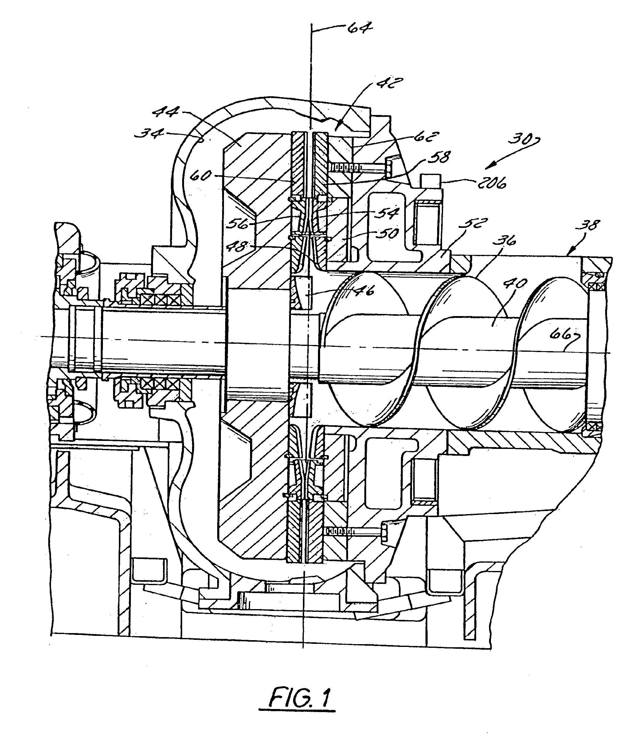
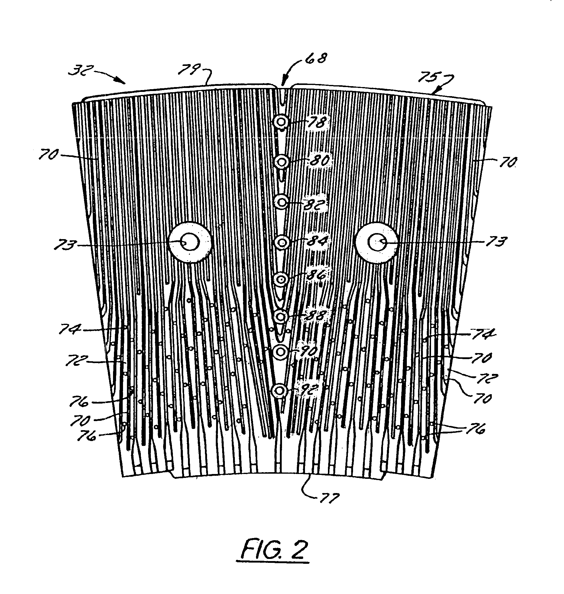
[0049]FIGS. 1-3 illustrate a refiner 30 to which the invention is applicable. The refiner 30 can be a refiner of the type used in thermomechanical pulping, refiner-mechanical pulping, chemithermomechanical pulping, or another type of pulping or fiber processing application. The refiner 30 can be a counter rotating refiner, a double disk or twin refiner, or a conical disk refiner known in the industry as a CD refiner.

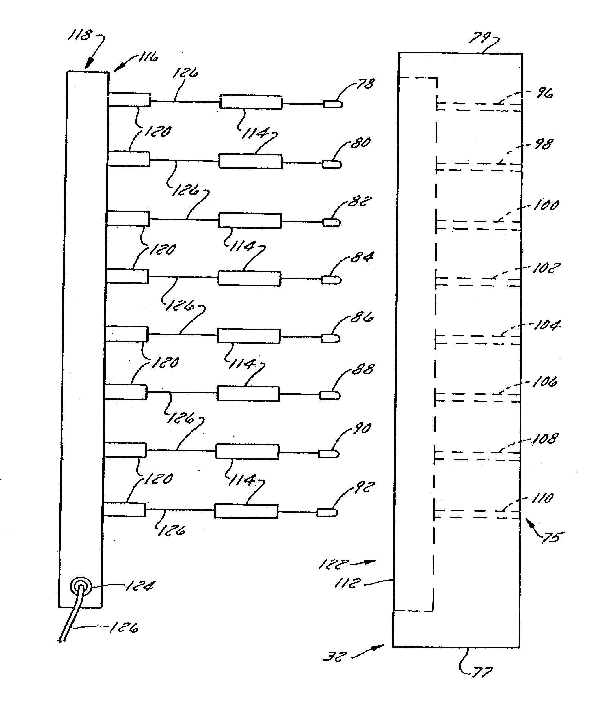
[0050]The refiner 30 has a refiner disk or refiner disk segment 32 (FIG. 2) carrying at least one sensor for sensing a parameter in the refining zone during refiner operation. The refiner 30 has a housing or casing 34 and an auger 36 mounted therein which urges a stock slurry of liquid and fiber introduced through a stock inlet 38 into the refiner 30. The auger 36 is carried by a shaft 40 that rotates during refiner operation to help supply stock to an arrangement of treating structure 42 within the housing 34 and a rotor 44. An annular flinger nut 46 is generally in lin...


PUM

PropertyMeasurementUnit
heightaaaaaaaaaa
thicknessaaaaaaaaaa
response timeaaaaaaaaaa

Abstract

A sensor, sensor disk, sensor measurement correction system, and method used in measuring a parameter in the refining zone. The sensor includes a spacer that spaces its sensing element from the disk. In one preferred embodiment, the spacer is made of an insulating material that insulates the sensing element from the thermal mass of the disk to prevent the thermal mass from affecting sensor measurement. The sensor includes a housing carried by the spacer that, in turn, carries the sensing element. Where the sensing element is a temperature sensing element, the housing is thermally conductive and the housing and spacer enclose the sensing element. Each sensor is disposed in the refining surface, preferably in its own separate bore in the disk and flush with or below axial refiner bar height. Signals from one or more sensors are processed by a processing device linked to a module containing calibration data that is applied to make sensor measurements more accurate. The module holds calibration data from sensors that are precalibrated before the sensor disk in which they are assembled is shipped, along with the module, to a fiber processing plant where the disk is installed in a refiner and the module connected to the processing device. In one preferred embodiment the sensor or sensors are carried by a sensor module that can be a removable segment of a refiner disk.

Description

CROSS REFERENCE TO RELATED APPLICATION[0001]This application is a continuation application of presently U.S. application Ser. No. 09 / 520,778, filed Mar. 8, 2000 and entitled “Refiner Disk Sensor and Sensor Refiner Disk,” now U.S. Pat. No. 6,502,774, the entirety of which is incorporated herein by reference.FIELD OF THE INVENTION[0002]The present invention relates to a sensor, a sensor refiner disk, a system for increasing the accuracy of a measurement made from a parameter sensed in the refining zone, and a method of improving the accuracy of the measurement made.BACKGROUND OF THE INVENTION[0003]Many products we use everyday are made from fibers. Examples of just a few of these products include paper, personal hygiene products, diapers, plates, containers, and packaging. Making products from wood fiber, fabric fiber and the like, involves breaking solid matter into fibrous matter. This also involves processing the fibrous matter into individual fibers that become fibrillated or fray...

Claims


Application Information

Patent Timeline
Patent Type & Authority Patents(United States)
IPC IPC(8): D21D1/30D21D1/00B02C7/02B02C7/04B02C7/11B02C7/12
CPCB02C7/02B02C7/11D21D1/306D21D1/002D21D1/30B02C7/12
Inventor JOHANSSON, OLA M.WULF, TIMOTHY L.
Owner J & L FIBER SERVICES
Why Eureka
Try Eureka