
Metal gasket and a material for its manufacture and a method for their manufacture

a technology of metal gaskets and metal parts, applied in the direction of piston rings, machines/engines, sealing arrangements of engines, etc., can solve the problems of unavoidable inclusion formation, and achieve the effects of excellent workability, marked strength increase, and complicated shap

Inactive Publication Date: 2005-05-17
HONDA MOTOR CO LTD +1
View PDF9 Cites 12 Cited by
  • Summary
  • Abstract
  • Description
  • Claims
  • Application Information

AI Technical Summary

Benefits of technology

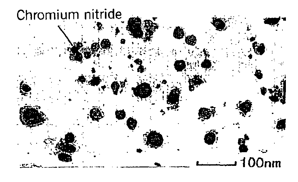
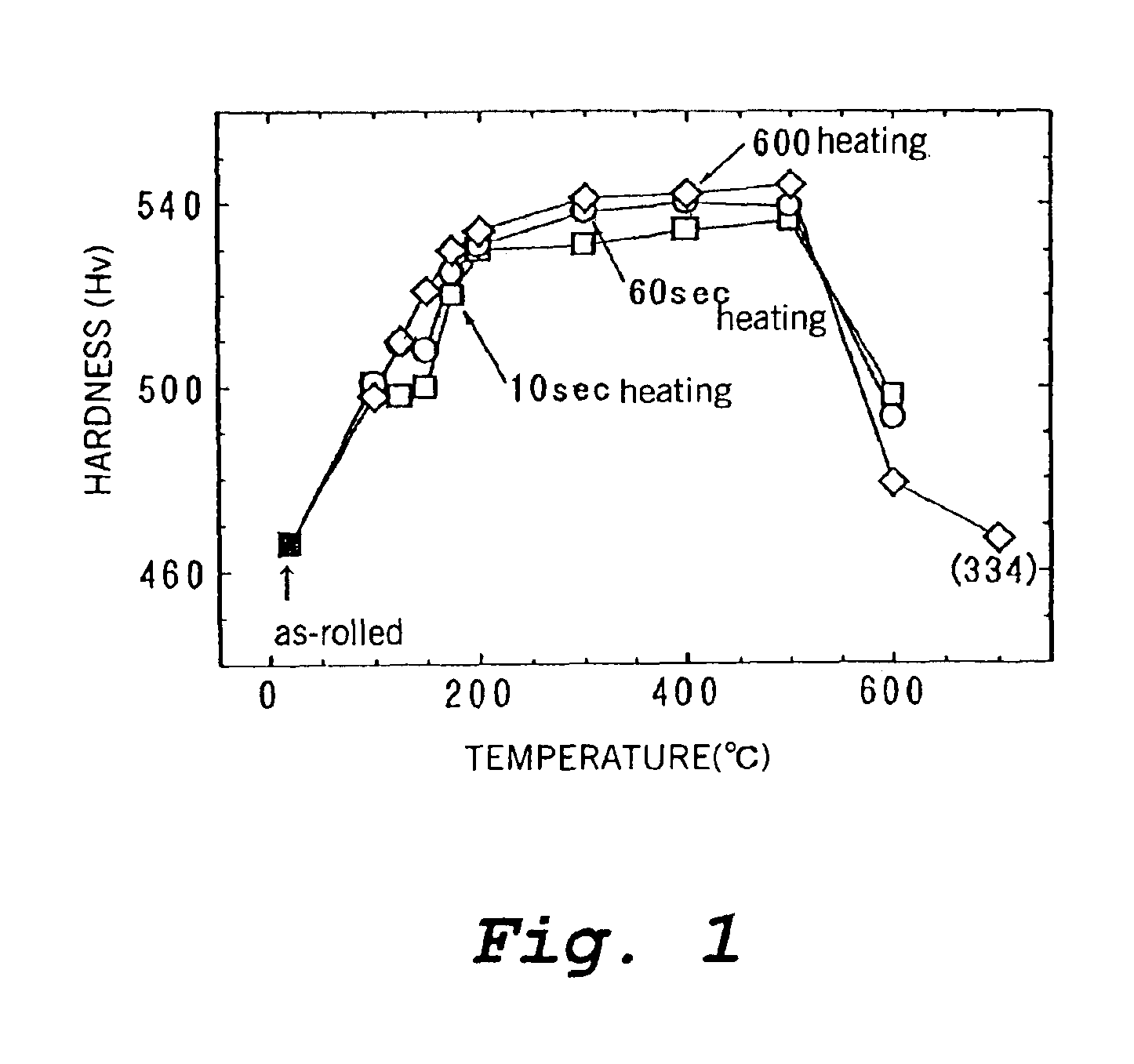
[0028]A stainless steel which is useful for manufacturing a metal gasket which is produced in this manner has excellent workability, and it can be worked into a complicated shape. In addition, when the stainless steel is subsequently subjected to heat treatment at a temperature of 200-500° C., its strength is markedly increased by age hardening (namely, precipitation strengthening) resulting from precipitation of chromium nitride, and its fatigue properties are also improved.
[0029]This age hardening can be achieved by heat treatment at a temperature up to about 350° C. which is carried out during the step of rubber coating in the manufacture of a metal gasket, so separate heat treatment just for the purpose of age hardening is not necessary. Therefore, a high strength metal gasket having excellent fatigue properties can be manufactured by the same manufacturing process as one which does not utilize precipitation strengthening (without it being necessary to have a separate heat treatment step) while suppressing the formation of defects at the time of bead formation.

Problems solved by technology

The stainless steel may contain inclusions which are unavoidably formed in its manufacture.

Method used


Image

  • Metal gasket and a material for its manufacture and a method for their manufacture
  • Metal gasket and a material for its manufacture and a method for their manufacture
  • Metal gasket and a material for its manufacture and a method for their manufacture

Examples


examples

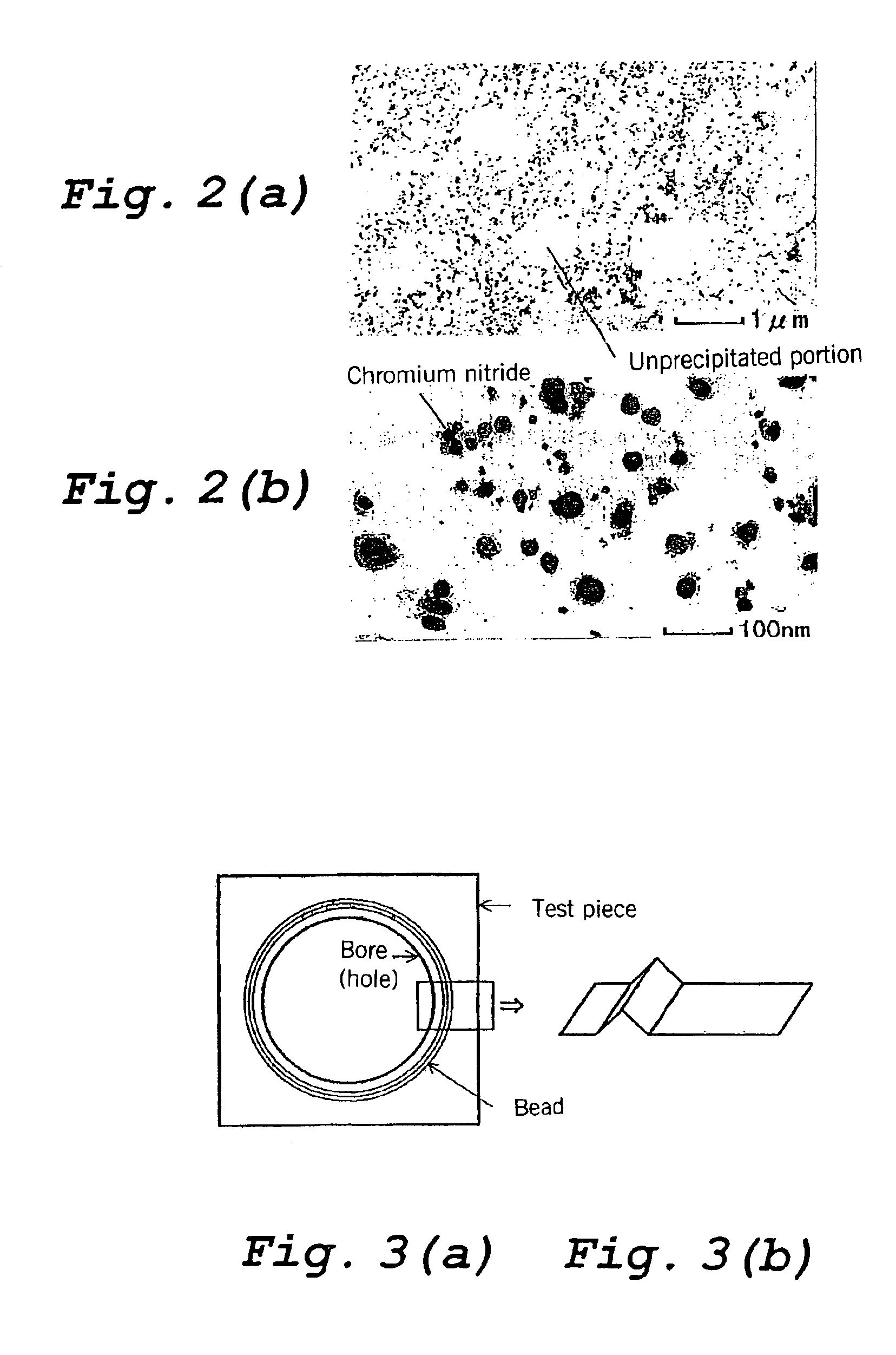
[0071]Stainless steels having the compositions shown in Table 1 were melted in a vacuum melting furnace and hot rolled and then repeatedly subjected to annealing and cold rolling. The resulting cold rolled steel sheets were subjected to final annealing under conditions selected from a temperature of 700-1100° C. and a heating time of 1-600 seconds, and then temper rolling was performed. The sheet thickness (t) after temper rolling was made 0.2 mm in all cases. The temper rolled steel sheets were cut to 170×170 mm, and the resulting test pieces were press formed using a prescribed die designed to form beads having the cross-sectional shape shown in the plan view and the perspective view of FIGS. 3(a) and 3(b), respectively, which had an annular shape having a diameter of approximately 60 mm, and finally subjected to aging at 300° C. for 1 minute.

[0072]In addition, a test piece was taken from the stainless steel sheet after each of final annealing, temper rolling, and aging and subjec...


PUM

PropertyMeasurementUnit
average grain diameteraaaaaaaaaa
temperatureaaaaaaaaaa

Abstract

This invention relates to a stainless steel gasket having markedly improved strength and fatigue properties due to precipitation strengthening. Its composition comprises C: at most 0.03%, Si: at most 1.0%, Mn: at most 2%, Cr: 16.0%-18.0%, Ni: 6.0%-8.0%, N: at most 0.25%, if necessary Nb: at most 0.30%, and a remainder of Fe and unavoidable impurities. After cold rolling, final annealing is carried out, and after a structure is formed of recrystallized grains with an average grain diameter of at most 5 μm having an area ratio of 50-100% and an unrecrystallized portion having an area ratio of 0-50%, a metal gasket is formed by steps including temper rolling with a reduction of at least 30% to make the area ratio of a strain induced martensite phase at least 40%, and forming and heat treatment at 200-350° C. The metal gasket has a duplex phase structure of at least 40% martensite in which chromium nitride is precipitated and a remainder of austenite, or it has a single phase structure of martensite in which chromium nitride is precipitated, and it has Hv of at least 500.

Description

METAL GASKET AND A MATERIAL FOR ITS MANUFACTURE AND A METHOD FOR THEIR MANUFACTURE[0001]This application is a continuation of International Patent Application No. PCT / JP02 / 04136 filed Apr. 25, 2002. This PCT application was not in English as published under PCT Article 21(2)TECHNICAL FIELD[0002]This invention relates to a metal gasket and particularly a metal gasket for an engine of an automobile or a motorcycle or the like, to a stainless steel for use in its manufacture, and to a method for their manufacture.[0003]Below, the present invention will be explained in particular using a metal gasket for an engine as an example, but a metal gasket according to the present invention is not limited thereto.BACKGROUND ART[0004]An engine gasket referred to as a head gasket is a sealing member which is mounted between a cylinder head and a cylinder block and which prevents leakage of combustion gas or engine cooling water or oil.[0005]In the past, as a head gasket, a composite type gasket ha...

Claims


Application Information

Patent Timeline
Patent Type & Authority Patents(United States)
IPC IPC(8): C22C38/58C22C38/00C22C38/48C21D8/02C22C38/02C22C38/04
CPCC21D8/0205C22C38/02C22C38/04C22C38/48C22C38/58C22C38/001C21D8/0236C21D8/0273C21D2211/004C21D2211/008Y10S148/908Y10T428/31707
Inventor ADACHI, KAZUHIKOISHIYAMA, SEISHIGOSHOKUBO, KENICHIKATSURAI, TAKASHI
Owner HONDA MOTOR CO LTD
Learn More