Vibration control device, stage device and exposure apparatus

a technology of vibration control device and stage device, which is applied in the direction of motor/generator/converter stopper, dynamo-electric converter control, instruments, etc., can solve the problems of increased rigidity, difficult controllability, and deterioration of vibration removal performance capability, so as to reduce the footprint of the exposure apparatus, reduce the cost, and reduce the effect of the vibration control devi

Inactive Publication Date: 2005-05-17
NIKON CORP
View PDF7 Cites 28 Cited by
  • Summary
  • Abstract
  • Description
  • Claims
  • Application Information

AI Technical Summary

Benefits of technology

[0014]In order to reduce a footprint of an exposure apparatus and/or reduce the cost, it is desirable to provide a smaller vibration control device, and particularly a smaller air cushion portion. However, in the case of the device of FIG. 17(A), for example, as in the vibration control device 931′ shown in FIG. 18(A), if a gas chamber 969′ with a small internal volume is formed by using a housing 961′ with a height lower than that of the housing 961, a compact vibration control device is formed. However, rigidity increases as an ai...

Problems solved by technology

However, rigidity increases as an air spring becomes shorter, so vibration from the floor is easily transmitted to the support target object OB, and an vibration removal performance capability deteriorates.
In addition, if the internal pressure is not made high, controllability becomes difficult.
In particular, in this structure, rigidity in the gravity direction is small, but rigidity in a horizontal direction and a twisting direction is strong, so a sufficient damping effect of floor vibration, i.e., a vibration removal effect, could not have been sufficiently obtained.
However, in the case of the vibration control device holding a large apparatus such as an exposure apparatus, an object weighing approximately 10 tons is supported at three or four locations, so the weight corresponding to approximately three tons for one location needs...

Method used


Image

  • Vibration control device, stage device and exposure apparatus
  • Vibration control device, stage device and exposure apparatus
  • Vibration control device, stage device and exposure apparatus

Examples


first embodiment

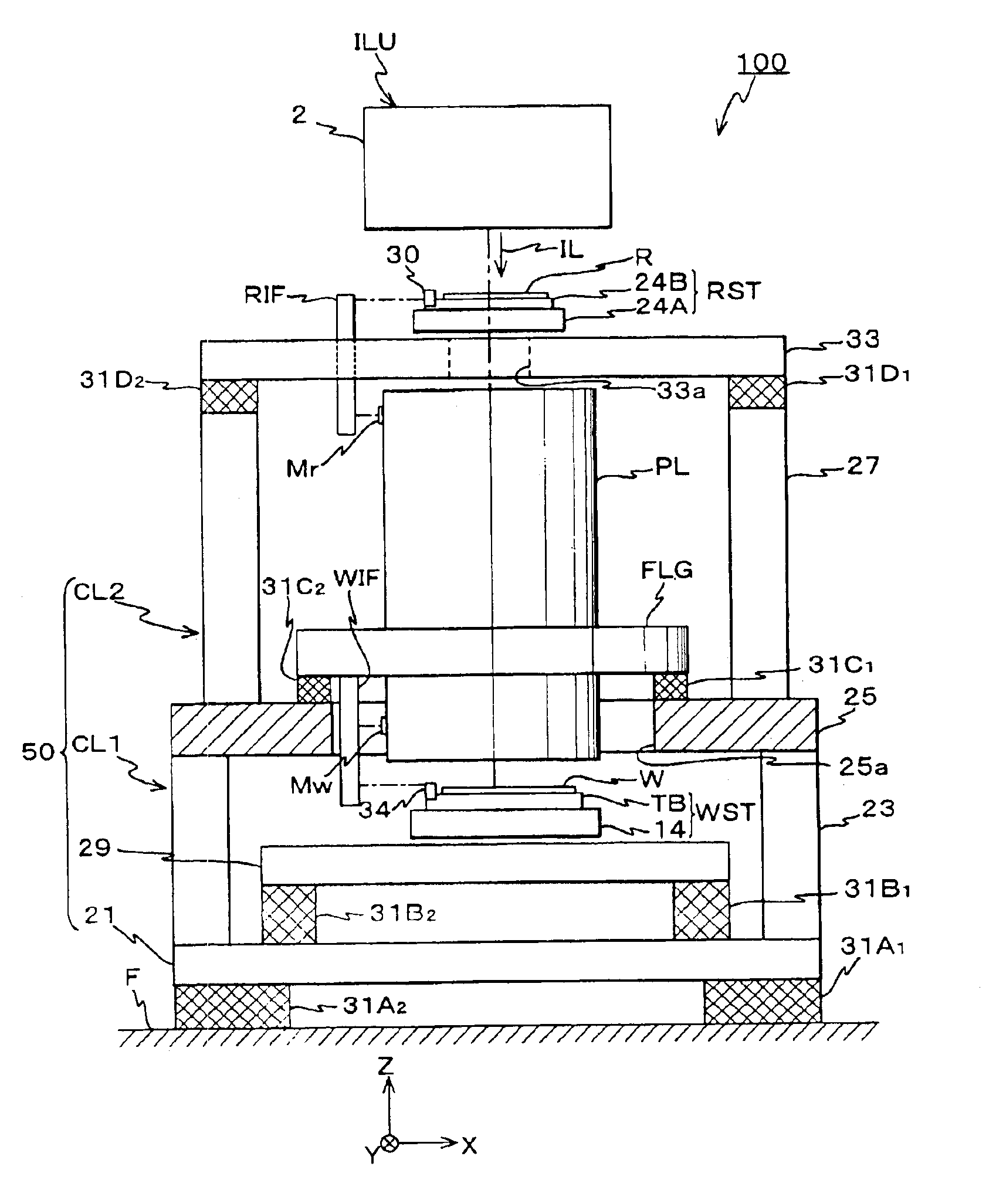
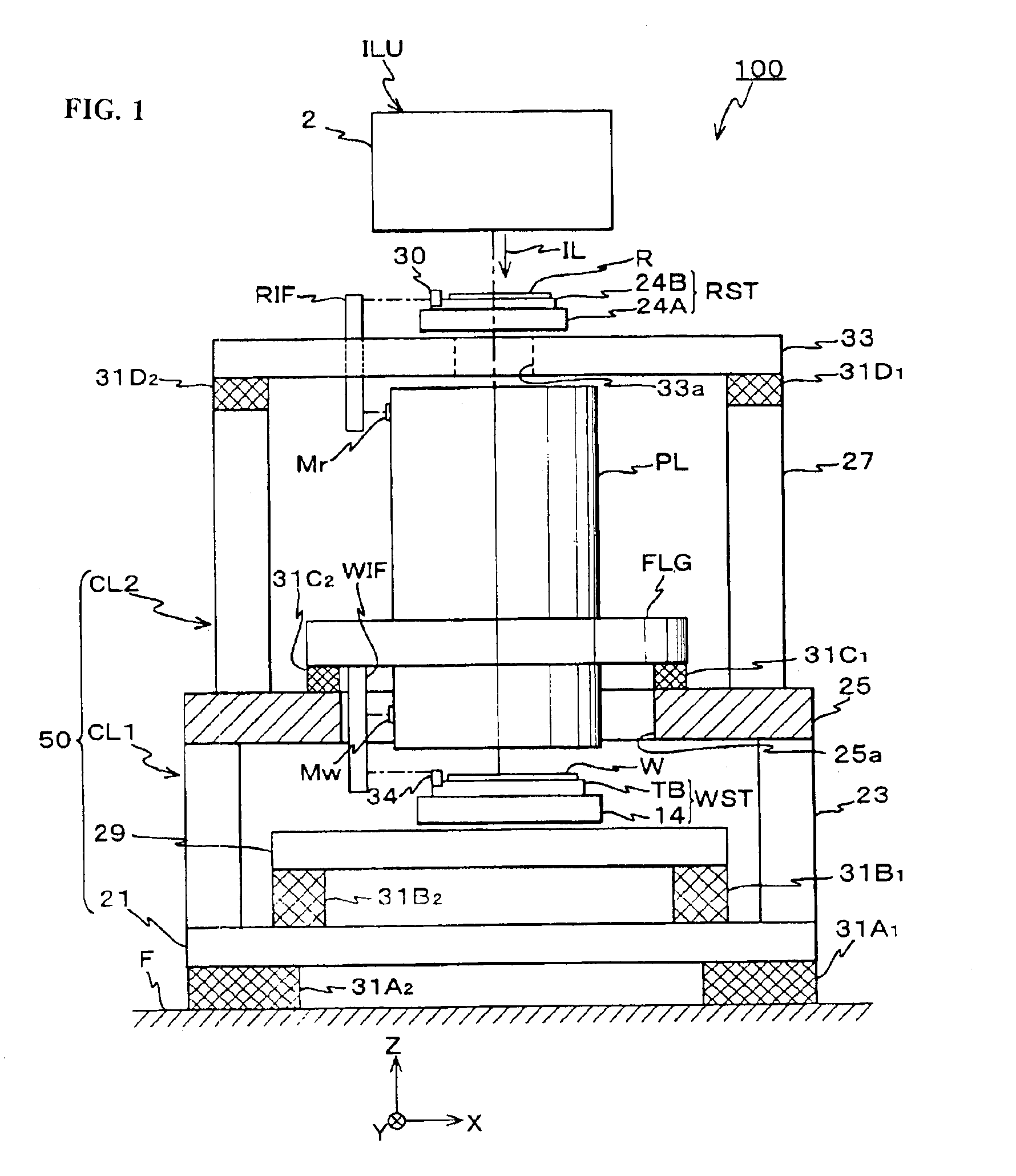
[0068]The following explains a first exemplary embodiment of this invention based on FIGS. 1-7(B). In FIG. 1, an overall structure of an exposure apparatus 100 of the first embodiment is schematically shown. This exposure apparatus 100 is a step-and-scan type scanning exposure apparatus, i.e., a so-called scanning stepper which synchronously moves a reticle R as a mask and a wafer W as a photosensitive object (or substrate) in a one-dimensional direction and transfers a circuit pattern formed in the reticle R to each shot region on the wafer W via a projection optical system PL.

[0069]The exposure apparatus 100 is provided with an illumination unit ILU which illuminates a slit-shaped rectangular illumination region on the reticle R with uniform irradiation by exposure illumination light (hereafter referred to as “illumination light”) as an energy beam, a reticle stage RST as a mask stage holding the reticle R, a projection optical system PL which projects the illumination light IL em...

second embodiment

[0184]Next, the second embodiment of this invention is described referring to FIG. 12. The exposure apparatus of the second embodiment has a feature that, instead of one of the vibration control devices 31A, 31B, 31C and 31D provided at parts of the body of the exposure apparatus 100 of the above-described first embodiment, a vibration control device 431 shown in FIG. 12 is used as a vibration control device. Other structures are similar to those of the first embodiment. Therefore, to avoid duplication of explanation, while the vibration control device 431 is mainly described, the structures that are the same as the first embodiment will be described using the same reference symbols.

[0185]As shown in FIG. 12, the vibration control device 431 of the second embodiment is equipped with an air mount part 451 that supports the supported object OB (the supported object OB is the same as the one in the first embodiment) from below, a piston mechanism 53 that is positioned adjacent to the a...

third embodiment

[0198]Next, a third embodiment of this invention is described referring to FIG. 13. The exposure apparatus of the third embodiment has a feature that, instead of one of the vibration control devices 31A, 31B, 31C and 31D provided at each part of the body of the exposure apparatus 100 of the above-described first embodiment, the vibration control device 531 shown in FIG. 13 is used as the vibration control device. Other structures are similar to those of the first embodiment. Therefore, to avoid duplication of explanation, while the vibration control device 531 is mainly described, the structural parts that are the same as the first embodiment will be described using the same reference symbols.

[0199]The vibration control device 531 of the third embodiment is, as shown in FIG. 13, provided with an air mount portion 551 that supports the supported object OB from below, a piston mechanism 53 provide adjacent to the air mount portion 551 that has the second gas chamber 79 connected via a...


PUM


Abstract

In order to remove vibration or improve a vibration control effect, and achieve device size reduction, an adjusting device is provided in which a weight of a support target object is supported by a pressure of an internal gas of a first chamber gas via a holding member and which adjusts a position in a gravity direction of the holding member by driving a movable member which changes an internal volume of the first gas chamber by changing an internal volume of a second gas chamber based on a state change of at least one of first and second gas chambers. Because of this, when the holding member is displaced in the gravity direction because of the vibration or the like, as the movable member is driven by the adjusting device, the holding member is maintained at an original position. Additionally, the movable member does not contact the support target object, so it does not directly deform the support target object, and the support target object is only driven by the change of the internal volume of the gas chambers; thus, even if the rigidity of the gas within the first gas chamber is high, there will be no problem regarding transmission of vibrations.

Description

INCORPORATION BY REFERENCE[0001]This application is based on Japanese Patent Application 2002-218157 filed Jul. 26, 2002, the disclosure of which is incorporated herein by reference in its entirety.BACKGROUND OF THE INVENTION[0002]1. Field of Invention[0003]This invention relates to a vibration control device, a stage device, and an exposure apparatus, and more specifically to a vibration control device which holds an object and controls vibration, a stage device provided with the vibration control device, and an exposure apparatus having the stage device.[0004]2. Description of Related Art[0005]Conventionally, in a lithographic process which manufactures a semiconductor element, a liquid crystal display element, or the like, it is known to use a step-and-repeat type reduction projection exposure apparatus (so-called stepper) or a step-and-scan type scanning projection exposure apparatus (so called scanning stepper). The stepper transfers a pattern formed in a mask or a reticle (her...

Claims


Application Information

Patent Timeline
IPC IPC(8): F16F15/023F16F15/027F16F15/03G03F7/20G03F7/22H01L21/027
CPCF16F15/0275G03F7/709G03F7/70833F16F15/03H01L21/027
Inventor NISHI, KENJI
Owner NIKON CORP
Why Eureka
Try Eureka