
Inverter transformer to light multiple lamps

Inactive Publication Date: 2005-05-17
MINEBEA CO LTD
View PDF7 Cites 25 Cited by
  • Summary
  • Abstract
  • Description
  • Claims
  • Application Information

AI Technical Summary

Benefits of technology

[0009]The present invention has been made in light of the circumstances, and it is an object of the present invention to provide a small-size, low-cost multiple lamp inverter transformer.
[0016]The inverter transformer of the present invention is capable of lighting a plurality of CCFLs at the same time. Also, voltages induced at the secondary windings are polarized identical with one another, and are evened up therebetween thus allowing the withstand voltage to be kept low. Consequently, the number of components is decreased resulting in a downsizing and cost reduction of the apparatus.

Problems solved by technology

With the open magnetic circuit structure, since the number of the inverter transformer increases with an increase of the number of the CCFLs by one-to-one ratio, the inverter transformer is increased in size as a whole, and the cost is pushed up.
And, with the closed magnetic circuit structure, although a plurality of CCFLs can be discharged by one inverter transformer, variation in the discharging operation occurs between the CCFLs, and also the inverter transformer is damaged by excess current.
The problem of the variation in the discharging operation between the CCFLs can be solved by inserting a ballast capacitor in series between the CCFLs, but this decreases power efficiency and increases variation in the CCFL current.
Furthermore, this results in an increased number of components and increased cost of production.
However, the following problem is associated with the inverter transformer.

Method used


Image

  • Inverter transformer to light multiple lamps
  • Inverter transformer to light multiple lamps
  • Inverter transformer to light multiple lamps

Examples


first embodiment

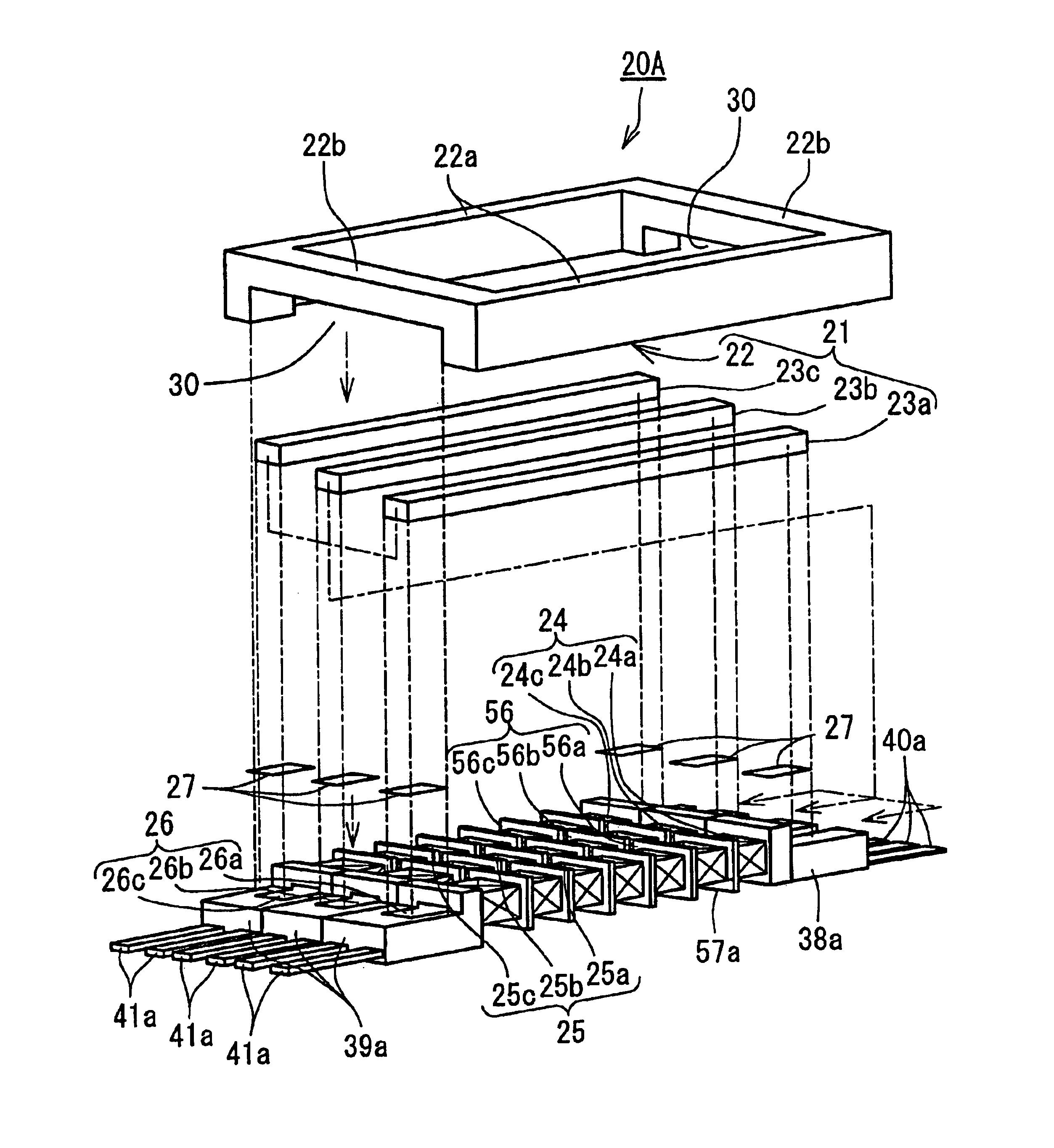
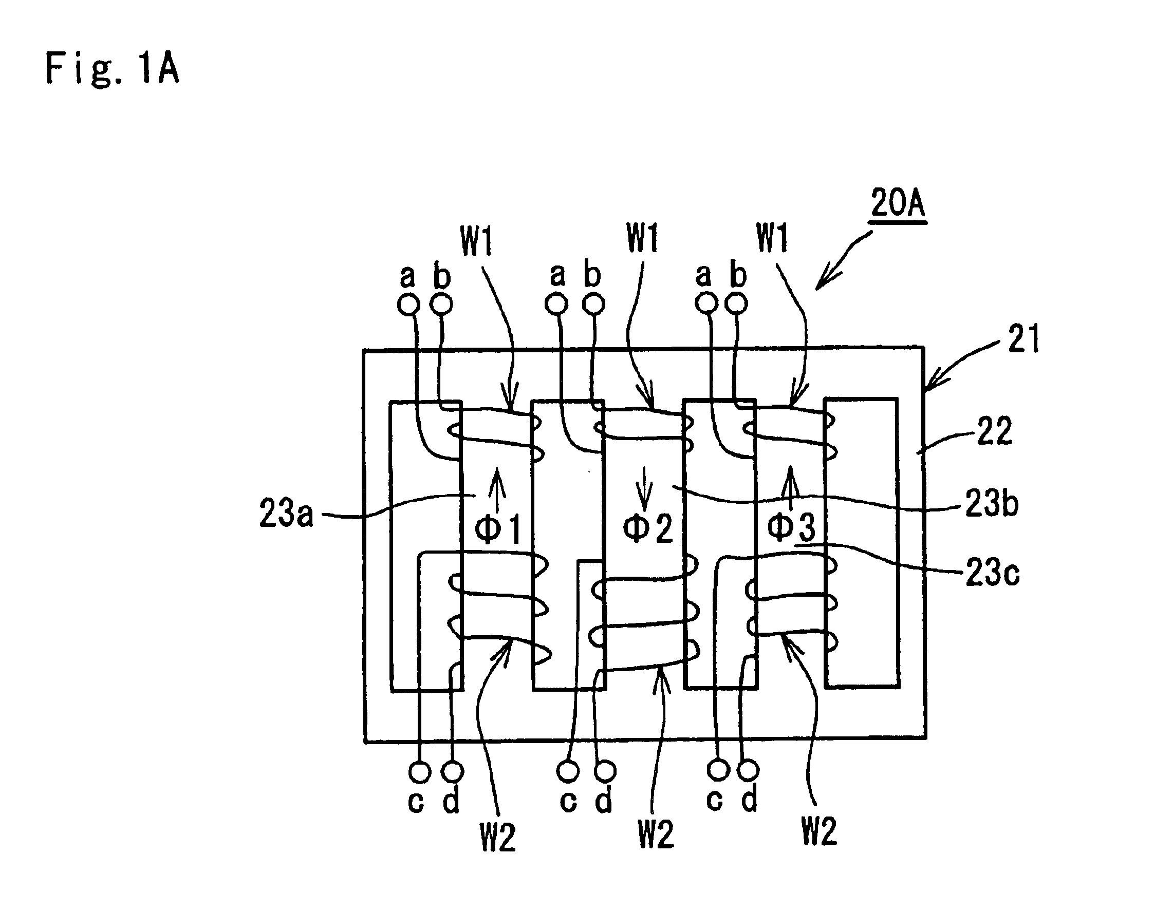
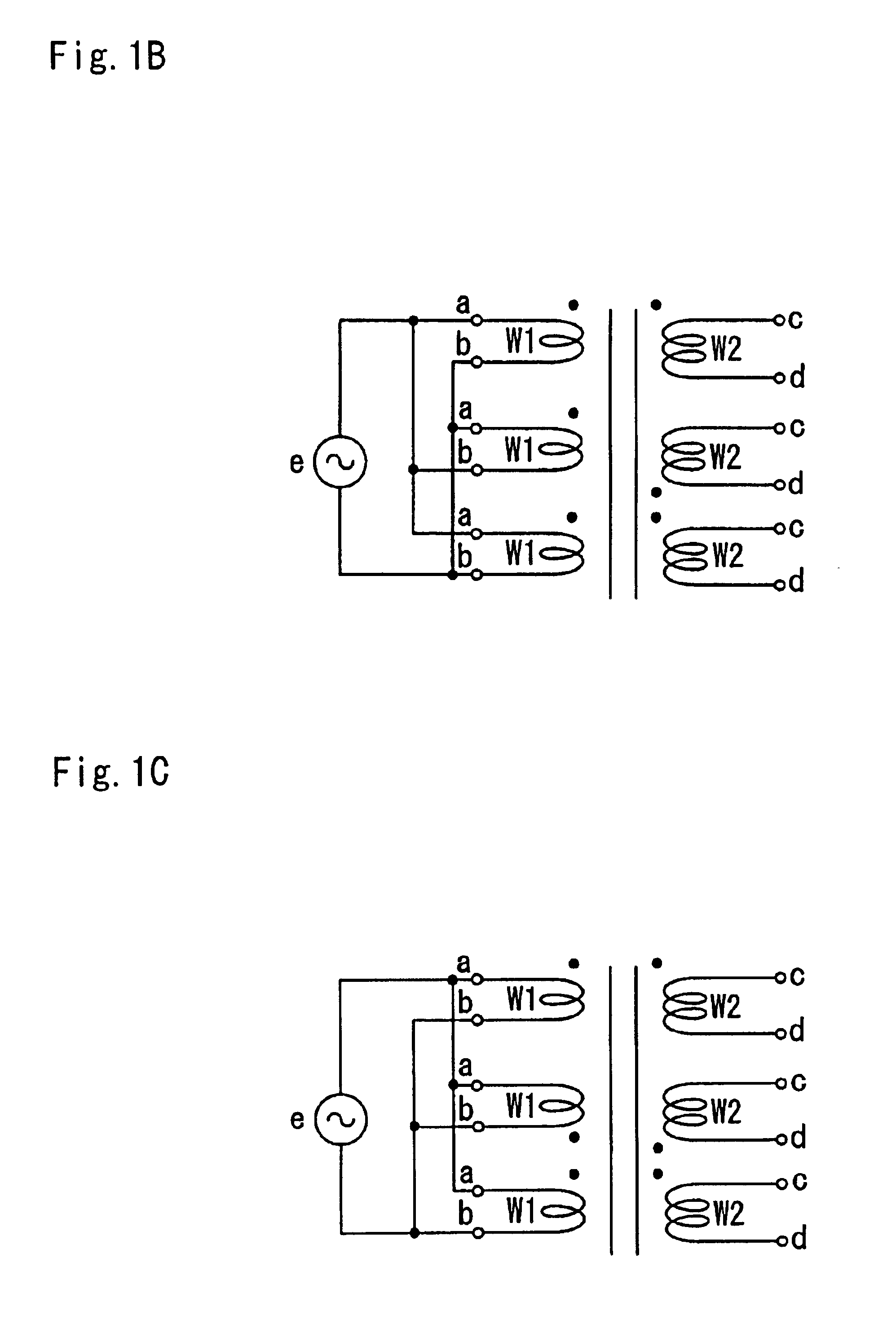
[0027]the present invention will hereinafter be described with reference to FIGS. 1A to 1C. An inverter transformer 20A is adapted to light three CCFLs and comprises a magnetic core 21 consisting of a frame-core 22 shaped substantially rectangular and three I-cores 23a, 23b and 23c disposed inside and coupled to the frame-core 22 so as to provide a predetermined leakage inductance. The I-cores 23a, 23b and 23c have respective primary and secondary windings W1 and W2 provided therearound.

[0028]Currents, which flow in two primary windings W1 provided respectively around the I-cores 23a and 23c (hereinafter referred to as first group as appropriate) located not adjacent to each other, generate respective magnetic fluxes Φ1 and Φ3 flowing in the same direction. The magnetic fluxes Φ1 and Φ3 generated by the two primary winding W1 of the first group and a magnetic flux Φ2, which is generated by current flowing in a primary winding W1 provided around the I-core 23b (hereinafter referred t...

second embodiment

[0033]the present invention will now be described with reference to FIGS. 2A and 2B. An inverter transformer 20B is adapted to light six CCFLs and comprises a magnetic core 21 consisting of a frame-core 22 shaped substantially rectangular and six I-cores 23a, 23b, 23c, 23d, 23e and 23f disposed inside and coupled to the frame-core 22 so as to provide a predetermined leakage inductance. The I-cores 23a, 23b, 23c, 23d, 23e and 23f have respective primary and secondary windings W1 and W2 provided therearound.

[0034]Currents, which flow in three primary windings W1 provided respectively around three I-cores 23a, 23c, 23e (hereinafter referred to as first group as appropriate) located not adjacent to one another, generate respective magnetic fluxes Φ1, Φ3 and Φ5 flowing in the same direction. Currents, which flow in another three primary windings W1 provided respectively around three I-cores 23b, 23d, 23f (hereinafter referred to as second group as appropriate) located not adjacent to one...


PUM


Abstract

An inverter transformer includes: a frame-core shaped substantially square; a plurality of I-cores disposed inside and coupled to the frame-core so as to provide a predetermined leakage inductance; and a plurality of primary and secondary windings provided respectively around the I-cores. The I-cores are divided into first group cores located not adjacent to one another and second group cores located not adjacent to one another but adjacent respectively to the first group cores. Magnetic fluxes generated in the first group cores flow in the same direction, magnetic fluxes generated in the second group cores flow in the same direction that is opposite to the direction of the magnetic fluxes generated in the first group cores, and respective voltages induced at secondary windings provided respectively around the first and second group cores are polarized identical with each other.

Description

BACKGROUND OF THE INVENTION[0001]1. Field of the Invention[0002]The present invention relates to an inverter transformer, and more particularly to an inverter transformer adapted to gain a high voltage by means of leakage inductance.[0003]2. Description of the Related Art[0004]In recent years, a liquid crystal display (hereinafter referred to as “LCD”) has been widely used as a display device for a personal computer or the like, replacing a cathode ray tube, what we call “CRT”. Unlike the CRT, the LCD does not emit light by itself, and therefore requires a lighting apparatus for lighting a screen, such as backlight or frontlight system. Cold-cathode fluorescent lamps (hereinafter referred to as “CCFL”) are generally used as light sources for the system and simultaneously discharged and lighted.[0005]For lighting and discharging the CCFLs, an inverter circuit is generally employed, which generates a high-frequency voltage of about 60 kHz and about 1600 V at the start of discharging. ...

Claims


Application Information

Patent Timeline
IPC IPC(8): H01F27/24H01F38/00H01F30/04H01F30/00H01F38/10H01F3/00H01F3/12H01F27/26
CPCH01F27/24H01F38/10H01F30/04H01F3/12H01F27/263
Inventor SUZUKI, SHINICHI
Owner MINEBEA CO LTD
Learn More