Internal combustion engine idle control

a technology of internal combustion engine and idle control, which is applied in the direction of electric control, ignition automatic control, machines/engines, etc., can solve the problem of reducing the speed of response to changes in inlet airflow, and achieve the effect of reducing engine power

Inactive Publication Date: 2005-05-24
VISTEON GLOBAL TECH INC
View PDF10 Cites 6 Cited by
  • Summary
  • Abstract
  • Description
  • Claims
  • Application Information

AI Technical Summary

Benefits of technology

[0011]The invention permits the air inlet valve to be operated in such a way that the air flow is increased more rapidly to the engine than would be the case if the air inlet valve were moved only to the position which would result in the desired steady state air flow. The additional engine demand can therefore be met more quickly by the engine.
[0025]The closing of the air inlet valve according to the exponential decay factor is useful because the natural damping effect to changes in air flow through the air inlet will be lower at higher air flow speeds, and therefore also at higher engine speeds.
[0027]It is particularly helpful if the airflow is allowed to temporarily overshoot that necessary to meet the expected engine demand. This results in a quicker initial rise in the air flow volume towards the desired level.
[0031]Alternatively or additionally, the engine control unit may also compensate for a temporary overshot in engine speed by temporarily reducing the amount of injected fuel or the timing of injection events.
[0032]Thus, the engine power can be reduced below that which would otherwise prevail if the engine spark angle during the period of air flow overshoot were not varied.

Problems solved by technology

However, a large intake manifold volume to engine displacement ratio and a lower idling speed both reduce the speed of response to changes in inlet airflow.

Method used


Image

  • Internal combustion engine idle control
  • Internal combustion engine idle control
  • Internal combustion engine idle control

Examples


Embodiment Construction

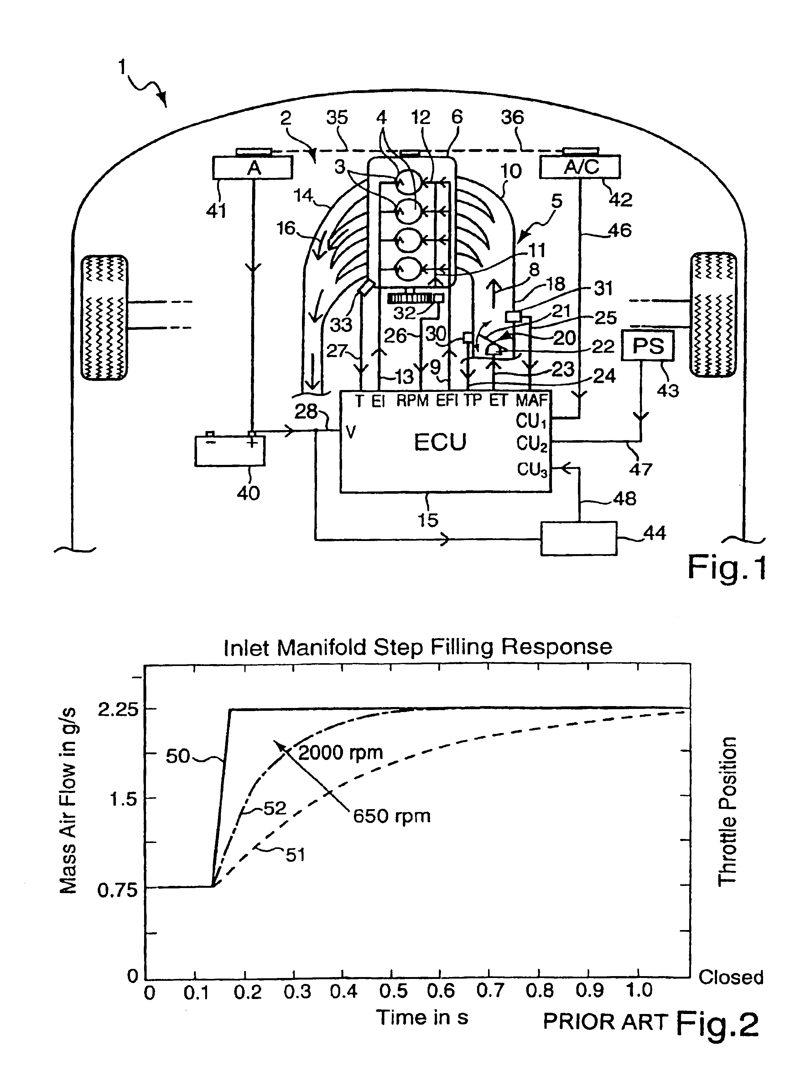
[0038]Referring now to FIG. 1, shown therein is part of a motor vehicle 1, for example a car, with an engine 2. In this example, the engine 2 is a spark ignition engine, although the invention in its broadest scope is also applicable to compression ignition engines. The engine 2 has a number of cylinders 4, each with a spark plug 3, situated above a crank case 6. The engine 2 also has an air inlet system 5 that supplies inlet air 8 to the cylinders 4 via an inlet manifold 10.

[0039]Fuel 11 may be supplied to each of the cylinders 4 via a fuel injector 12. The fuel injection may either direct injection or indirect injection. Each fuel injector 12 is controlled by an electronic fuel injection (EFI) control signal received along a control signal line 9 from a microprocessor-based engine control unit (ECU) 15. Similarly, each spark plug 3 is energized under the control of an electronic ignition signal (EI) sent from the ECU 15 along an ignition control signal line 13.

[0040]It should be n...


PUM


Abstract

The present invention relate to idle control in an internal combustion engine and particularly to the control of the air supply to the engine during engine idling. An engine control unit (ECU) monitors the operation of ancillary consumer units to calculate an engine demand depending at least partly on the operation of these units. The ECU also monitors the engine idling speed to determine if the expected engine demand can be met at this engine idling speed. When the engine demand exceeds that available at the idling speed, the ECU determines a desired degree of opening of an air inlet valve to meet the expected engine demand. The ECU is arranged first to open the air inlet valve to a position at which the steady state airflow would exceed that necessary to meet the expected engine demand, and then closes the air inlet valve towards the calculated desired opening.

Description

BACKGROUND OF THE INVENTION[0001]1. Field of the Invention[0002]The present invention relates to idle control in an internal combustion engine, and particularly the control of the air supply to the engine during engine idling.[0003]2. Related Art[0004]In order to improve engine torque at high engine speeds, automotive internal combustion engines have been developed which have a larger air intake manifold volume for a given engine displacement. At the same time, engine accessories and other ancillary consumer units in motor vehicles are constantly being improved and in some cases converted from being mechanically driven to being electrically driven. This has the effect of lowering the idle load placed on the engine, and hence the minimum desirable engine speed.[0005]It therefore becomes more important that an engine should respond quickly to any sudden increase in engine load at idle speeds, for example owing to a sudden increase in alternator demand or power steering demand, in orde...

Claims


Application Information

Patent Timeline
Patent Type & Authority Patents(United States)
IPC IPC(8): F02D37/00F02D41/08F02D41/00F02D37/02F02D9/10F02D9/08
CPCF02D37/02F02D41/083F02D41/0002F02D9/1055Y02T10/42Y02T10/18Y02T10/12Y02T10/40
Inventor SHEPPERSON, ADAM PETER
Owner VISTEON GLOBAL TECH INC
Why Eureka
Try Eureka