Enhanced high efficiency fuel cell/turbine power plant

a fuel cell and high-efficiency technology, applied in the field of fuel cell systems, can solve the problems of reducing efficiency, increasing the cost of power plant hardware, and inhibiting the use of internal reforming in the fuel cell, and achieve the effect of high efficiency

Active Publication Date: 2005-05-24
FUELCELL ENERGY INC
View PDF1 Cites 57 Cited by
  • Summary
  • Abstract
  • Description
  • Claims
  • Application Information

AI Technical Summary

Benefits of technology

[0009]In the embodiments of the invention to be disclosed hereinafter, the bypass assembly includes a controllable bypass valve having an input port receiving the expanded oxidant supply gas from the expansion cycle of the heat engine and first and second output sections for outputting the first and second expanded oxidant supply gas portions. The first section communicates with a line to the fuel cell and the second section communicates with a bypass line communicating with a line responsive to the cathode exhaust gas, the bypass line forming a part of the bypass assembly. The bypass assembly also includes a control scheme such as a gas flow detector and control for detecting the second expanded oxidant gas portion and for adjusting the bypass valve for controllably apportioning the first and second expanded oxidant gas portions. In this way, the compressor cycle of the heat engine and the fuel cell can be operated at their highest efficiencies.

Problems solved by technology

In this arrangement, the fuel cell is operated at a high pressure, which substantially increases the cost of the power plant hardware and inhibits the use of internal reforming in the fuel cell.
This further increases the plant cost and reduces efficiency, and subjects the fuel cell to potentially damaging pressure differentials in the event of plant upset.
Furthermore, the fuel cell pressure is coupled with gas turbine pressure, limiting the application to system designs where the gas turbine pressure is nearly matched with the fuel cell pressure.
This limits the usefulness of the system.

Method used


Image

  • Enhanced high efficiency fuel cell/turbine power plant
  • Enhanced high efficiency fuel cell/turbine power plant
  • Enhanced high efficiency fuel cell/turbine power plant

Examples


first embodiment

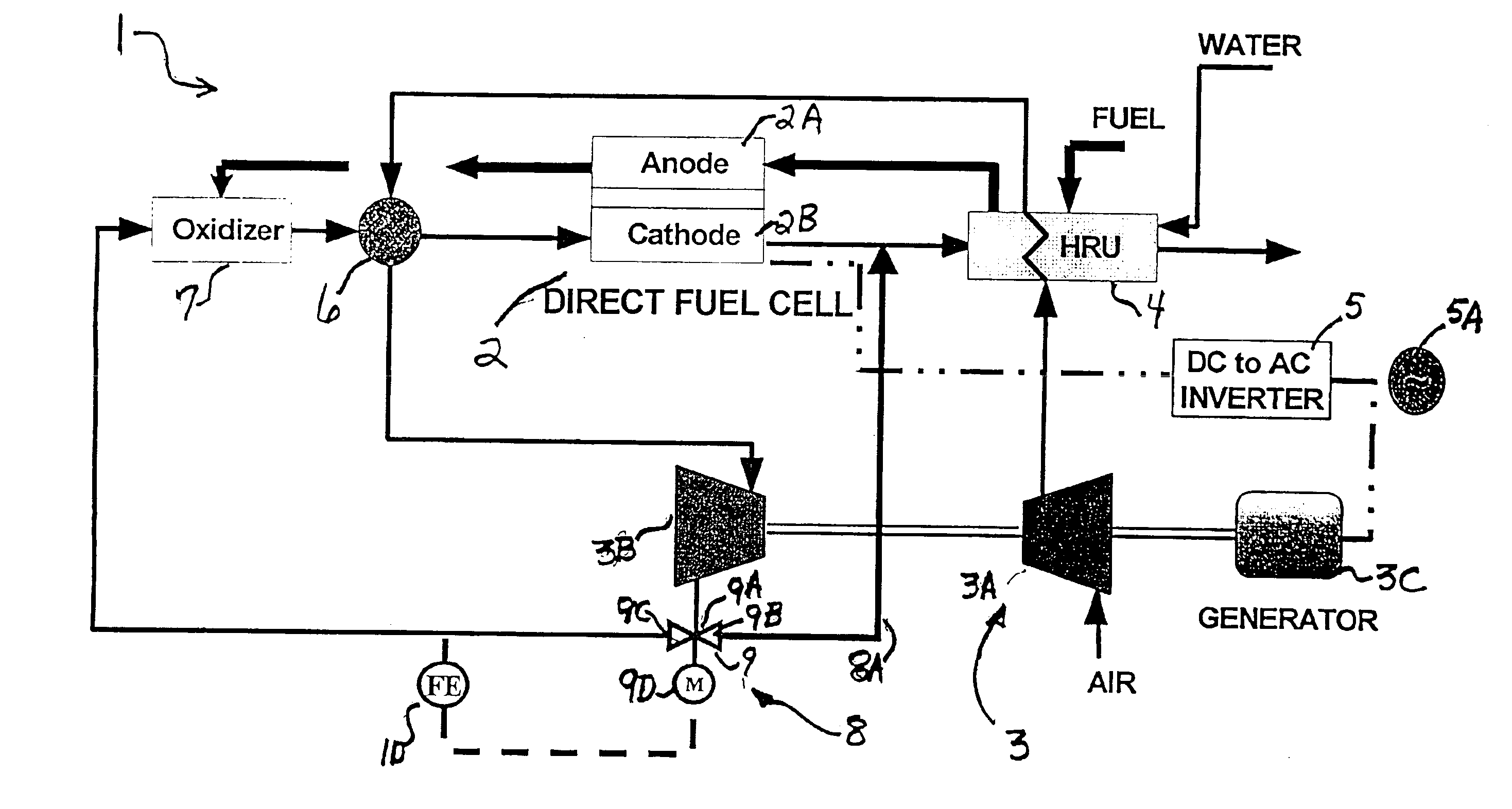
[0014]FIG. 1 shows a hybrid fuel cell system 1 in accordance with the principles of the present invention. The system 1 includes a high temperature fuel cell 2 having an anode section 2A and a cathode section 2B. As shown, the high temperature fuel cell 2 is an internally reforming or a direct carbonate fuel cell. However, an externally reforming carbonate fuel cell can also be employed. The DC output of the fuel cell 2 is fed to a DC to AC converter 5 to provide an AC output 5A.

[0015]The hybrid system 1 includes a heat engine 3, shown illustratively as a turbine generator, having a gas compressor section 3A for carrying out a gas compression cycle and a gas decompression or expansion section 3B for carrying out a gas expansion cycle. The heat engine 3 also includes a generator 3C coupled to the heat engine 3 for converting mechanical energy produced in the expansion cycle into electrical energy. Heat engines such as a gas turbine or a Sterling cycle engine may be employed as a typi...

second embodiment

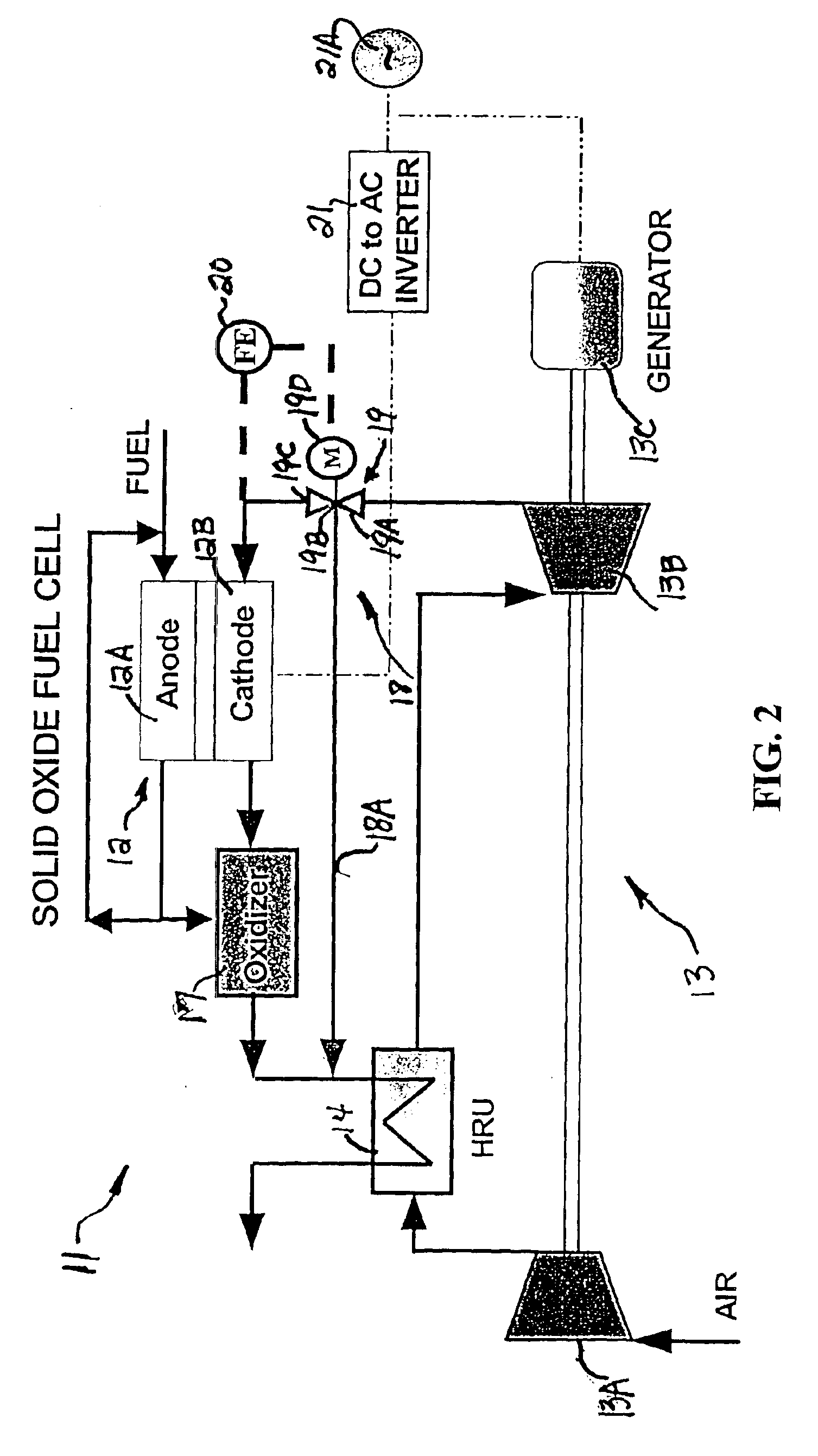
[0026]FIG. 2 shows a hybrid fuel cell system 11 in accordance with the principles of the present invention. In this embodiment, the high temperature fuel cell employed is a is a solid oxide fuel cell 12 having an anode section 12A and a cathode section 12B. As shown in FIG. 2, the solid oxide fuel cell 12 is an internally reforming solid oxide fuel cell. However, an externally reforming solid oxide fuel cell can also be employed. The DC output of the fuel cell 12 is fed to a DC to AC converter 21 to provide an AC output 21A.

[0027]The solid oxide hybrid system 11 comprises a heat engine 13, shown illustratively as a turbine generator, having a gas compressor section 13A for carrying out a gas compression cycle and a gas expansion section 13B for carrying out a gas expansion cycle. The heat engine 13 also includes a generator 13C coupled to the gas expansion section 13B for converting mechanical energy produced in the gas expansion cycle into electrical energy.

[0028]The solid oxide hy...


PUM

PropertyMeasurementUnit
temperatureaaaaaaaaaa

Abstract

A hybrid fuel cell system having a fuel cell and a heat engine having an expansion cycle and a compressor cycle and which is further adapted to include a bypass assembly for segmenting expanded oxidant supply gas from the expansion cycle of the heat engine into a first expanded oxidant supply gas portion and a second expanded gas portion and in which the first expanded oxidant supply gas portion is used for the fuel cell and the second expanded gas portion bypassed around the fuel cell.

Description

BACKGROUND OF THE INVENTION[0001]This invention relates to fuel cell systems and, in particular, to integrated fuel cell and gas turbine systems having enhanced efficiency.[0002]A fuel cell is a device which directly converts chemical energy stored in hydrocarbon fuel into electrical energy by means of an electrochemical reaction. Generally, a fuel cell comprises an anode and a cathode separated by an electrolyte, which serves to conduct electrically charged ions.[0003]A fuel cell may be combined with a heat engine such as a turbine generator to produce a high efficiency system, commonly called a hybrid system. In a conventional hybrid system, the fuel cell is typically situated in the position normally occupied by the combustor of the turbine generator so that air compressed by the turbine generator compressor section is heated and then sent to the fuel cell cathode section. In this arrangement, the fuel cell is operated at a high pressure, which substantially increases the cost of...

Claims


Application Information

Patent Timeline
Patent Type & Authority Patents(United States)
IPC IPC(8): H01M8/04H01M8/14H01M8/12H01M8/00
CPCH01M8/04014H01M8/04097H01M8/04111H01M8/04395H01M8/04425H01M8/04753H01M8/04776H01M8/04089Y02E60/526H01M8/0618H01M8/0637H01M2008/1293H01M2008/147H01M2250/402H01M2250/407Y02B90/12Y02E60/563Y02E60/50Y02E60/525Y02B90/10H01M8/04
Inventor WANG, ZHAO-HUIGHEZEL-AYAGH, HOSSEIN
Owner FUELCELL ENERGY INC
Why Eureka
Try Eureka