

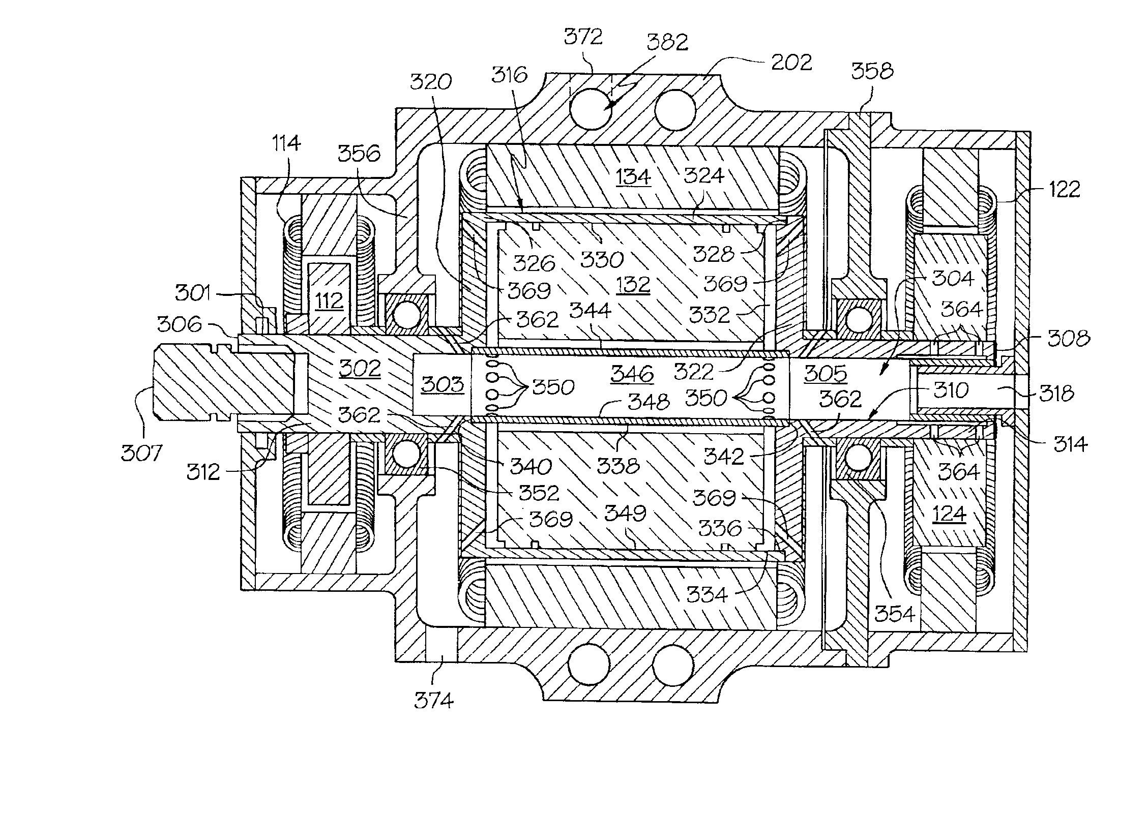
High speed generator with the main rotor housed inside the shaft
a generator and shaft technology, applied in the direction of magnetic circuit rotating parts, cooling/ventilation arrangement, magnetic circuit shape/form/construction, etc., can solve the problems of affecting the performance and manufacturing cost of the generator, imposing large centrifugal forces on various, and electrical components within the generator may generate heat due to electrical losses, etc., to improve the rotor dynamics, improve the rotor stability, and reduce the effect of material stress
- Summary
- Abstract
- Description
- Claims
- Application Information
AI Technical Summary
Benefits of technology
Problems solved by technology
Method used
Image

Examples
Embodiment Construction
[0016]Before proceeding with the detailed description, it is to be appreciated that for convenience of explanation the present embodiment is depicted and described as being implemented in a brushless AC (alternating current) generator,. However, the present invention is not limited to a brushless AC generator environment, but may be implemented in other AC generator designs needed in specific applications.
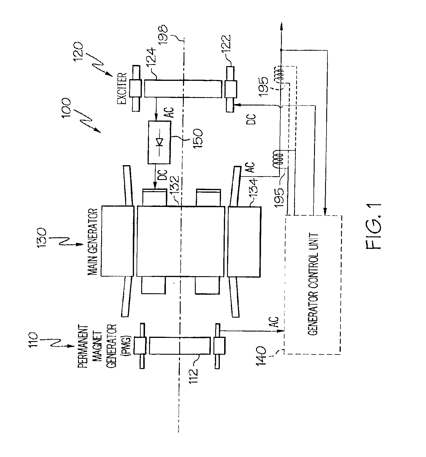
[0017]Turning now to the description, and with reference first to FIG. 1, a functional schematic block diagram of an exemplary high speed generator system 100 for use with a gas turbine engine such as that in an aircraft is depicted. This exemplary generator system 100, which is commonly known as a brushless AC generator, includes a permanent magnet generator (PMG) 110, an exciter 120, a main generator 130, a generator control unit 140, and one or more rectifier assemblies 150. During operation, a rotor 112 of the PMG 110, a rotor 124 of the exciter 120, and a rotor 132 of the main...
PUM
 Abstract
Description
Claims
Application Information