
Ultrasonic motor and guide apparatus having the same as driving source of movable body

a technology of ultrasonic motors and guide devices, applied in the direction of piezoelectric/electrostrictive/magnetostrictive devices, piezoelectric/electrostrictive/magnetostriction machines, piezoelectric/electrostrictive/magnetostriction device details, etc., can solve the problem of abrasion progressing in correspondence to deterioration of mechanical characteristics, causing no slippage, and not largely deteriorating

Inactive Publication Date: 2005-05-24
KYOCERA CORP +2
View PDF12 Cites 23 Cited by
  • Summary
  • Abstract
  • Description
  • Claims
  • Application Information

AI Technical Summary

Benefits of technology

[0027]An object of the present invention is to provide an ultrasonic motor in which a mechanical characteristic is not largely deteriorated due to a friction heat, an abrasion resistance is excellent and no slip is generated even when the ultrasonic motor is driven at a high speed.
[0028]Another object of the present invention is to provide a guide apparatus which has a compact size, can move a movable body at a high speed, can obtain a stable driving characteristic and has a long life time, by employing the ultrasonic motor as a driving source of the movable body.
[0030]The another object of the present invention is to provide a guide apparatus which can forecast an abrasion of a friction member in an ultrasonic motor and a drive transmitting member in a stage, caused by a slip between the ultrasonic motor and the stage, by detecting the slip.
[0031]Another object of the present invention is further to provide a guide apparatus provided with a control system which can prevent the abrasion from being generated.
[0032]Another object of the present invention is further to provide a guide apparatus which can obtain position data required for judging the slip without depending upon the non-contact type measuring device, and can achieve a simple structure of the apparatus.

Problems solved by technology

Further, the slip changes a contact state between the friction member and the drive transmitting member, and makes any one of them abnormally wear out.
The friction member 15a of the ultrasonic motor 15 employing the glass material such as the silica glass, the soda glass or the like has a small fracture toughness value, and has a risk that a chip or a fracture is generated when a crack is generated.
In addition, when driving the ultrasonic motor 15 at a high velocity, there is a case that a friction heat with the drive transmitting member 14 goes over 100° C. Since the zirconia based sintor is generally brittle against heat, there is a risk that an abrasion make progress in correspondence to deterioration in a mechanical characteristic or the like.
The high-alumina based sinter, for example, containing 99.5% by weight or more alumina content, has a very high hardness, however, the high-alumina based sinter is hard to be sintered and requires a high temperature sintering.
The abnormal abrasion makes the guide apparatus break down and makes the life time of the guide apparatus short beyond expectation, however, it is hard to forecast the life time of the guide apparatus.
In the conventional guide apparatus, since it is necessary that the non-contact type measuring means is always mounted to the apparatus for measuring the slip distance, there is a problem that the structure of the apparatus is made complicate and large size.
Further, there is accordingly a problem in view of a cost.
Accordingly, in order to measure the slip in the precise measuring apparatus and the drawing exposure apparatus in which a small occupied space is required, it becomes hard to design and there is a limitation in design.

Method used


Image

  • Ultrasonic motor and guide apparatus having the same as driving source of movable body
  • Ultrasonic motor and guide apparatus having the same as driving source of movable body
  • Ultrasonic motor and guide apparatus having the same as driving source of movable body

Examples


embodiment 1

[0062]In the ultrasonic motor 15 in accordance with the present invention, the friction member 15a mentioned above is formed by an alumina based sinter containing alumina as a main component and titanium carbide as a secondary component.

[0063]Although alumina has a high hardness (Vickers hardness Hv 18 GPa) and a high melting point (2100° C.), the titanium carbide to be added thereto has a higher hardness (Vickers hardness Hv of 28 GPa) and a higher melting point (3200° C.) than alumina, and a high toughness (fracture toughness; 6 MPam1 / 2). The alumina based sinter containing titanium carbide has characteristics of high friction coefficient, high abrasion resistance and high resistance against separation of grains due to abrasion.

[0064]The present invention utilizes alumina containing titanium carbide as the friction member of the ultrasonic motor, which can drive a drive transmitting member fixed to the side face of a stage as movable body. Since the contact face of the friction me...

example 1

[0076]In this example, friction members for ultrasonic motors were made of alumina based sinters containing titanium carbide in accordance with the present invention, and comparative friction members are also made of silica glass, a high purity alumina based sinter, a zirconia based sinter, and a silicon carbide based sinter. The alumina based sinters containing titanium carbide were prepared by formulating in various contents titanium carbide and aid components as shown in Table 1, and were provided for assembling a conventional type of ultrasonic motors as shown in FIG. 8. Experiments were carried out for determining the abrasion amounts of the friction members and of the drive transmitting members in driving the ultrasonic motors.

[0077]In the tests, the friction members were formed as a column having a length of 4.2 mm and a diameter of 3 mm, and a spherical contact face with a curvature radius of 7 mm. The vibration bodies of ultrasonic motors were produced of a piezoelectric ce...

embodiment 2

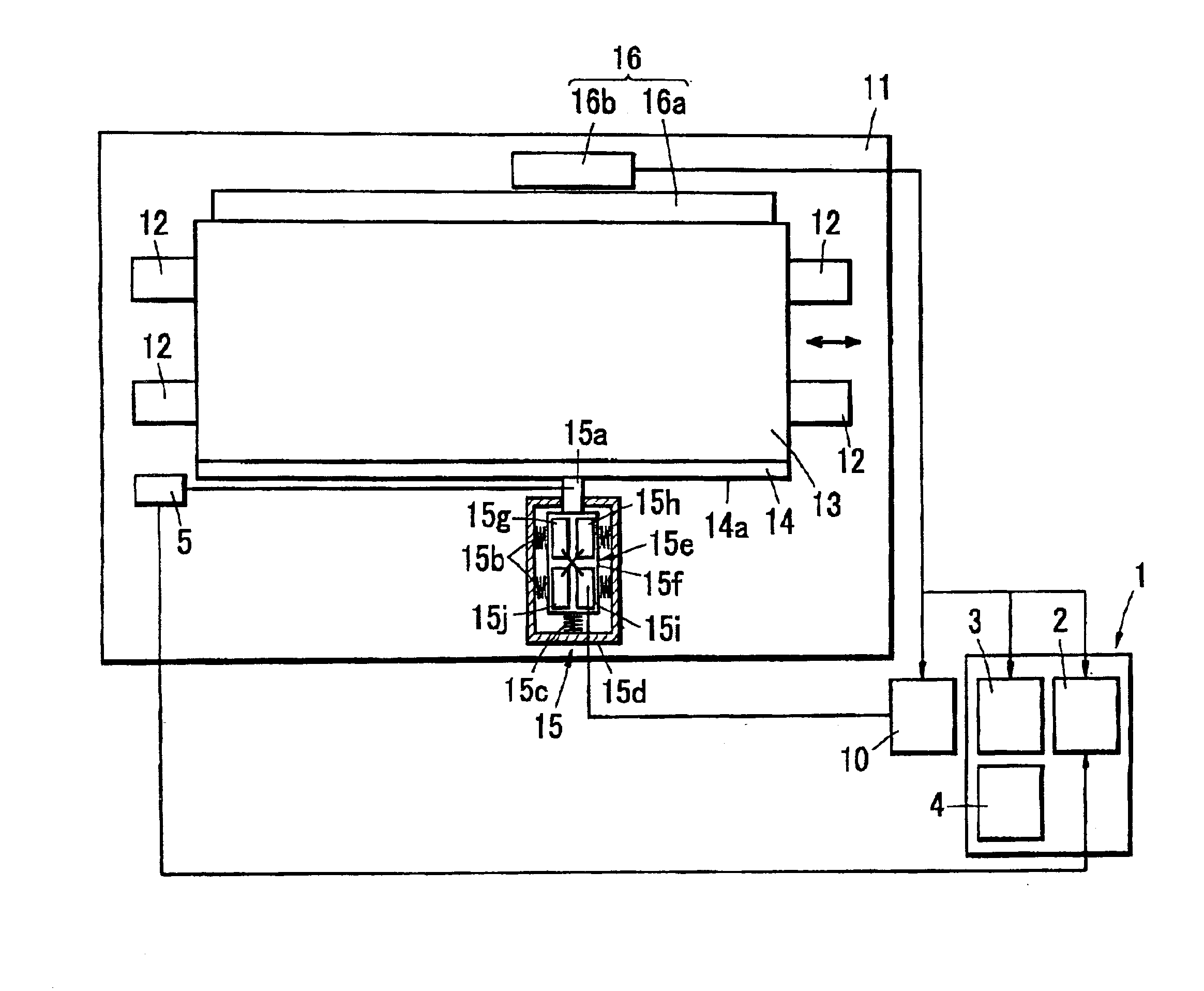
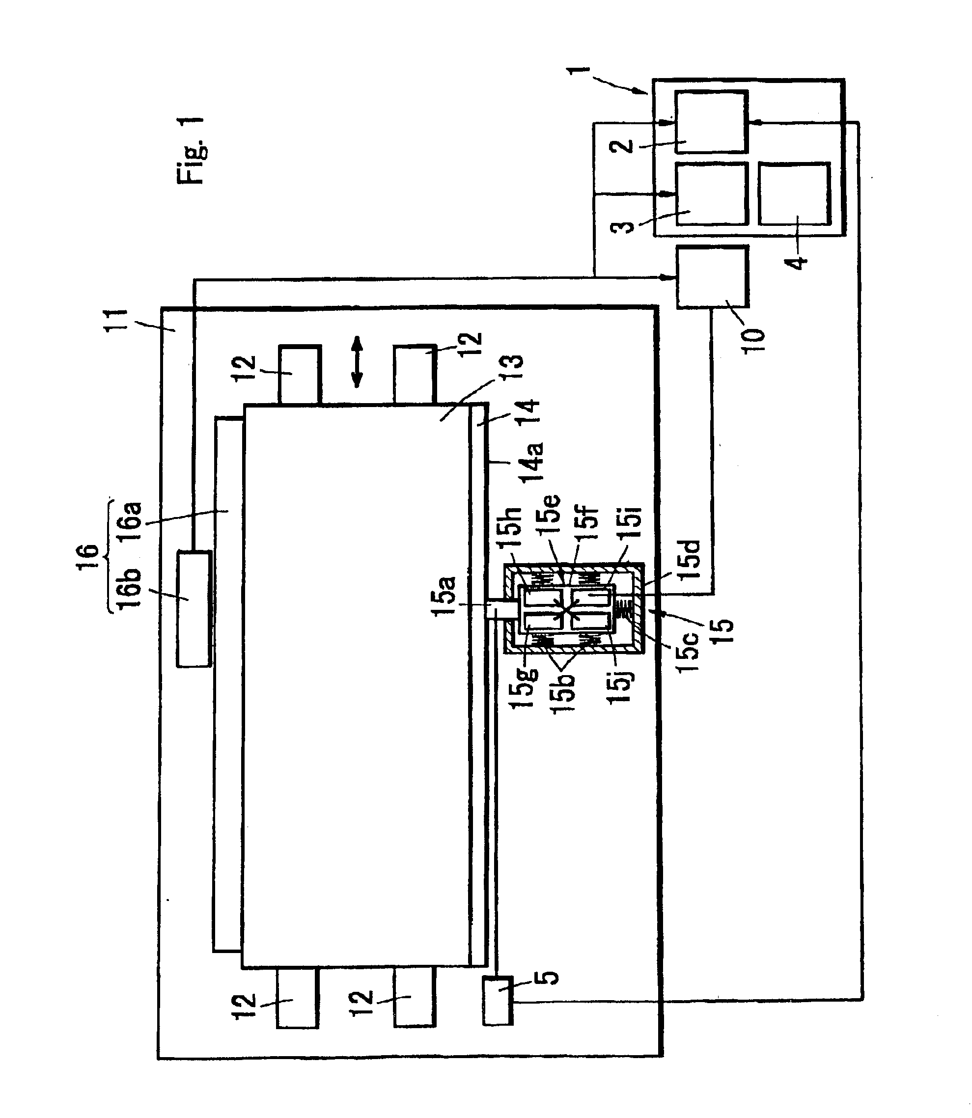
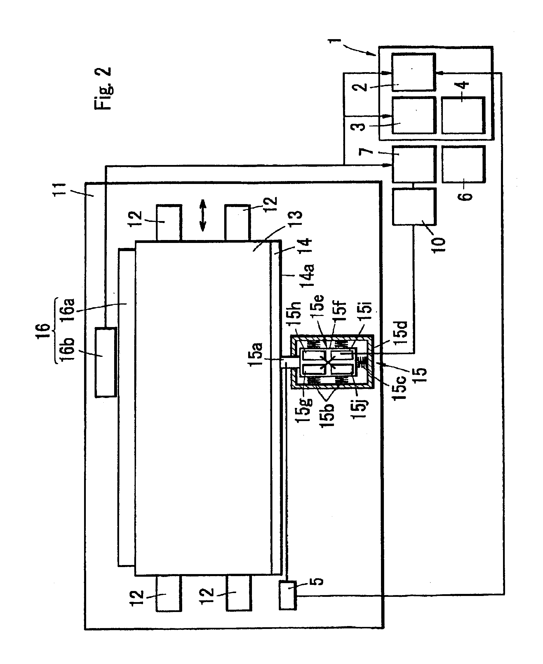
[0090]A guide apparatus using an ultrasonic motor as a driving source is structured, as shown in FIG. 1, such that to one side surface of a stage 13a a linear scale 16a is fixed in parallel to a guide member 12, the ultrasonic motor 15 is fixed to a position opposing to the drive transmitting member 14 on the base substrate 11, and the friction member 15a of the ultrasonic motor 15 is brought into contact with a driving surface 54a of the drive transmitting member 14 vertically.

[0091]The drive transmitting member 14 is provided in another side surface of the stage 13 in parallel to the guide member 12, and a measuring head 56b is provided at a position opposing to the linear scale 16a on the base substrate 11 in a lateral side of the guide apparatus, whereby a position detecting means 16 is constituted. In accordance with another aspect of the position detecting means 16, it is possible to utilize a system in which a reflection mirror is provided on the stage 13 and the position is ...


PUM


Abstract

In a guide apparatus having an ultrasonic motor as a driving source of a stage, it is intended to accurately comprehend a degree of abrasion between a friction member of a frictionally driven ultrasonic motor and a drive transmitting member of the stage. A guide apparatus is constructed by an ultrasonic motor, a stage capable of moving on the basis of a friction driving with the ultrasonic motor, a position detecting means for detecting a position of the stage, a driving control portion for outputting a driving command signal to the ultrasonic motor, a non-contact type measuring means for measuring a position information of a friction member in the ultrasonic motor, a slip distance measuring portion for calculating a slip distance of the friction member in the ultrasonic motor, and a monitoring portion 1 equipped with tangential force measuring portion for calculating a tangential force applied to a driving surface of the drive transmitting member in the stage on the basis of the friction driving with the ultrasonic motor.

Description

BACKGROUND OF THE INVENTION[0001]1. Field of the Invention[0002]The present invention relates to a friction member provided in an ultrasonic motor for transmitting a vibration of the ultrasonic motor to a movable body. The present invention relates to a guide apparatus in which a ultrasonic motor drives a movable body linearly or rotationally.[0003]2. Prior Art[0004]It is features of ultrasonic motors as power sources for controlling and driving use that a minimum amplitude by vibration is small in an order of nanometer, allowing for precise positioning with high revolution. The ultrasonic motors can provide a large driving force due to friction drive with a compact size. The ultrasonic motors have been conventionally utilized in rotation control systems including lens zoom mechanism for cameras and vibration alarms for wrist watches. In recent years the ultrasonic motors are applied to linear control systems.[0005]The ultrasonic motors can achieve high positioning accuracy during m...

Claims


Application Information

Patent Timeline
Patent Type & Authority Patents(United States)
IPC IPC(8): H01L41/09H02N2/08H10N30/20
CPCH01L41/0913H02N2/026H02N2/007H10N30/2023
Inventor KATOADACHI, KOSHIISHIMINE, YUSAKU
Owner KYOCERA CORP
Learn More