Surface-mount type antennas and mobile communication terminals using the same

Inactive Publication Date: 2005-05-24
PANASONIC CORP
View PDF8 Cites 19 Cited by
  • Summary
  • Abstract
  • Description
  • Claims
  • Application Information

AI Technical Summary

Benefits of technology

[0015]As another type of second feeder electrode, a feeder electrode provided on an inner wall face of a groove formed in the second principal face can be used and, thereby, ease of fabrication can be obtained. As a further type of second feeder electrode, such a feeder electrode can also be used that is provided on an inner wall of a groove formed at a portion of the side face, on which the fir

Problems solved by technology

As antennas used on such a portable remote terminal, surface-mount type antennas have frequently been used because of the terminal being limited in size.
However, productivity was poor because this process required cementing substrates together and, sometimes, great variations in characteristics were produced.
In addition, because of a difference of thermal expansion coefficient between the substrate and the feeder electrode, cracks were produced, or stress was accumulated, in the substrate, and, sometimes, variations in characteristics were produced.
Accordingly, this type of ant

Method used


Image

  • Surface-mount type antennas and mobile communication terminals using the same
  • Surface-mount type antennas and mobile communication terminals using the same
  • Surface-mount type antennas and mobile communication terminals using the same

Examples


exemplary embodiment 1

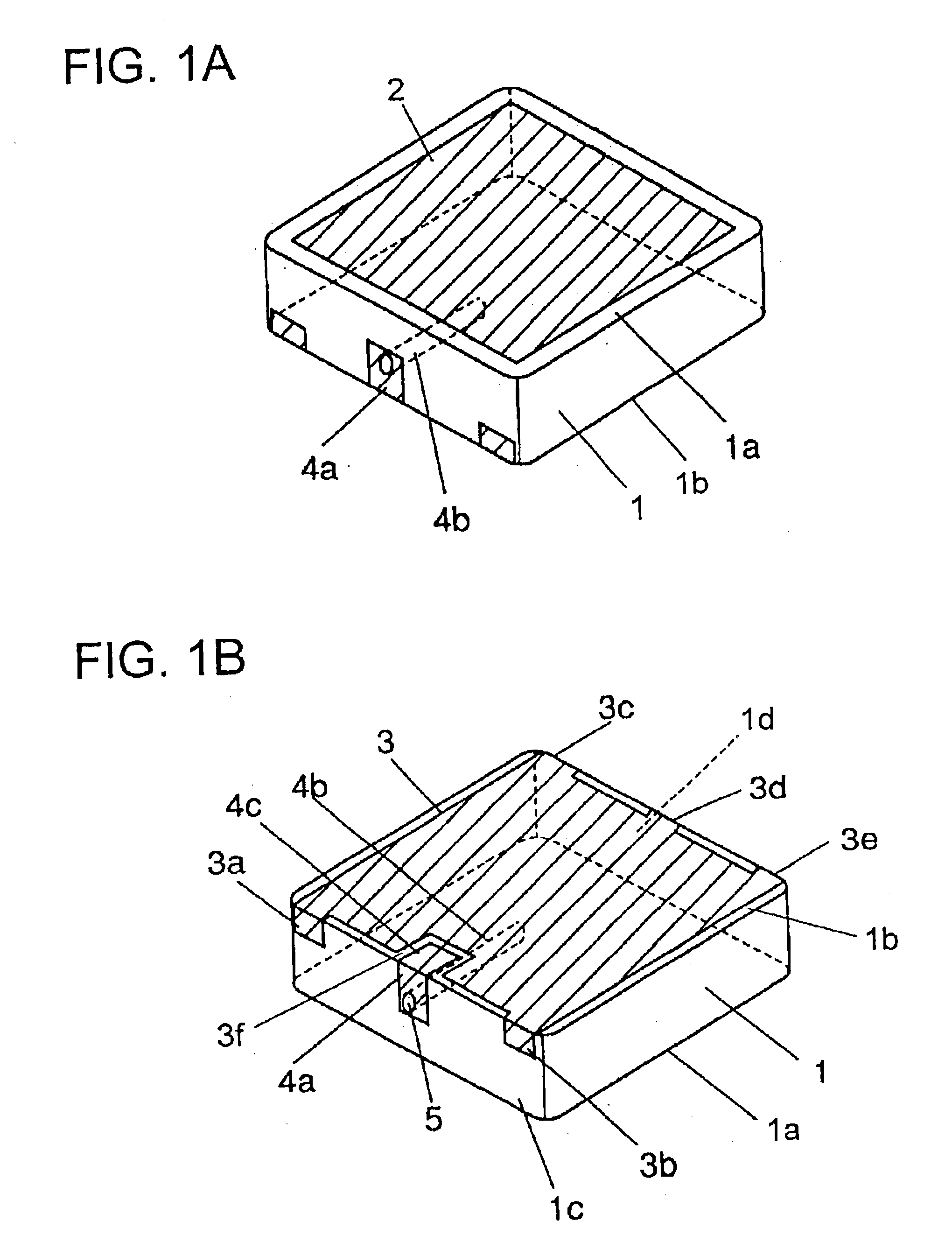
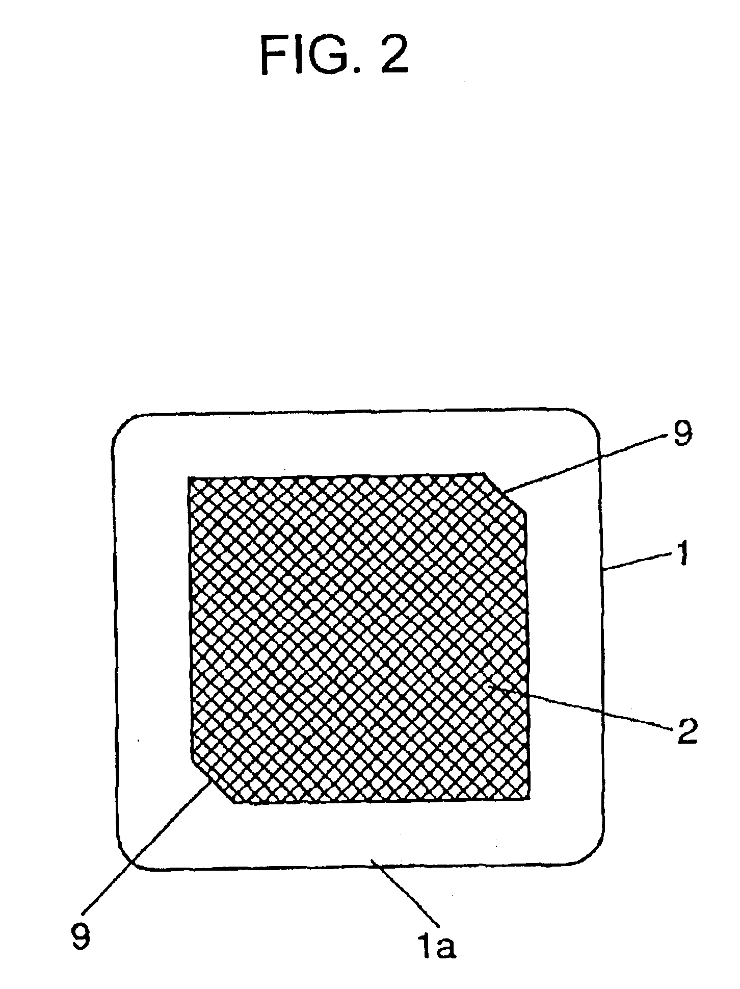
[0033]FIGS. 1, 2, 3, and 4 are a perspective view, a top appearance view, a plan view, and a side view, respectively, of a surface-mount type antenna of the present invention.

[0034]Main components of the present exemplary embodiment and electric characteristics thereof will be enumerated below:

1. Substrate

[0035](a) ∈r

[0036]In FIGS. 1, 2, 3, and 4, a substrate 1 is made of a dielectric material whose relative dielectric constant ∈r is preferably not smaller than 4 and not greater than 150 (more preferably, not smaller than 18 and not greater than 130). When relative dielectric constant ∈r is smaller than 4, the size of substrate 1 becomes too large and miniaturization of the antenna becomes unattainable. When relative dielectric constant ∈r is greater than 150, the operating frequency range of the antenna becomes too narrow. Then, the operating frequency deviates from a predetermined frequency range if there is produced a small difference in chemical composition or a small chip on ...

exemplary embodiment 2

[0081]FIG. 7 shows a perspective view of a surface-mount type antenna of the present invention.

[0082]There is provided a step portion 6 extended from side face 1c to principal face 1b of substrate 1 by cutting a portion off side face 1c and principal face 1b as shown in FIG. 7 to form feeder electrode 4a on one step face 4a′ of step portion 6 (hereinafter, “step face” means each of two faces along the principal face and along the side face at the stepped portion). By virtue of this structure, a signal fed into feeder electrode 4a produces electromagnetic coupling between the edge portion of feeder electrode 4a and radiator electrode 2, whereby a function as an antenna is obtained. At this time, since feeder electrode 4a is placed inwardly from the outside shape of substrate 1 because of the provision of step portion 6, it can have a more suitable and stable electrode arrangement in feeding signals into radiator electrode 2. Thus, stabilized antenna characteristics can be obtained.

[...

exemplary embodiment 3

[0084]FIG. 8 shows a perspective view of a surface-mount type antenna of exemplary embodiment 3 of the present invention.

[0085]Step portions 6a, 6b, 6c, 6d, and 6e equivalent to step portion 6 (FIG. 7) formed in exemplary embodiment 2 are provided extended from side faces 1c and 1d to principal face 1b as shown in FIG. 8. Then, fixed electrodes 3a, 3b, 3c, 3d, and 3e are provided on step faces 3a′, 3b′, 3c′, 3d′, and 3e′ of step portions 6a, 6b, 6c, 6d, and 6e.

[0086]In the surface-mount type antenna structured as described above, since soldered portions of the electrodes are recessed further inwardly from the circumference of substrate 1 than in embodiment 2, a higher strength can be obtained against bending or flexure of the substrate when the antenna is mounted on a printed board, whereby reliability of the antenna can be enhanced. Further, the size of the land pattern formed on a printed board on which the antenna of the present embodiment is mounted can be placed within the out...


PUM


Abstract

A surface-mount type antenna and a communication terminal using the same. A radiator electrode is provided on a first principal face of a substrate. A ground electrode is provided on the second principal face of the substrate. A first feeder electrode has at least a portion thereof provided on a side face and on the second principal face of the substrate. A second feeder electrode is provided on an inner wall face of a hole formed parallel to the first and second principal faces. The first feeder electrode and the ground electrode are kept in a non-contact state. The first feeder electrode and the second feeder electrode are in electrical contact. A mobile communication terminal using the surface-mount type antenna is small in size, exhibits small variations in characteristics, and provides high productivity and reliability.

Description

[0001]This application is a divisional application of application Ser. No. 09 / 960,379, filed Sep. 24, 2001 now U.S. Pat. No. 6,559,802.FIELD OF THE INVENTION[0002]The present invention relates to a surface-mount type antenna for use in a global positioning system, more particularly to a surface-mount type antenna mounted on a portable remote terminal, and to a mobile communication terminal using the same.BACKGROUND OF THE INVENTION[0003]A system having a global positioning system mounted on a portable remote terminal for transmitting information of the present position of the terminal to a specific party on the other end of the connection is being put to practical use. For example, when a carrier of the portable remote terminal meets an emergency (such as a traffic accident), the person can transmit information of his or her present position to a specific place (such as a rescue center) so as to take a necessary measure without delay.[0004]As antennas used on such a portable remote ...

Claims


Application Information

Patent Timeline
IPC IPC(8): H01Q1/38H01Q9/04H01Q21/30H01Q1/24H01Q21/28H01Q21/00H01Q13/08
CPCH01Q1/243H01Q1/38H01Q21/30H01Q21/28H01Q9/0407
Inventor GOTO, KAZUHIDEONAKA, YOSHIOYOSHINOMOTO, MAKOTOSAKITA, HIROMISASAKI, KATSUMISHIIBA, KENGO
Owner PANASONIC CORP
Why Eureka
Try Eureka