Heterodyne lateral grating interferometric encoder

a technology of interferometer and lateral grating, which is applied in the direction of interferometer, measurement device, instruments, etc., can solve the problems of inefficiency, high cost, and inability to adjust the alignment of all components, so as to reduce the sensitivity of differential path error sources, reduce the sensitivity to typical error sources, and reduce the effect of optical components

Inactive Publication Date: 2005-05-24
THE BOEING CO
View PDF5 Cites 22 Cited by
  • Summary
  • Abstract
  • Description
  • Claims
  • Application Information

AI Technical Summary

Benefits of technology

[0006]Unlike a Mach-Zender interferometer, the interferometer of the present invention does not require splitting the beam into two legs to produce the heterodyne modulation. In accordance with the present invention, the zero order beam from the AOM acts like the reference against which the higher order beams are interfered. Since all the beams travel through nearly identical optical paths , the sensitivity to differential path error sources is greatly reduced, thereby significantly reducing sensitivity to typical error sources such as vibration of optical components, air turbulence, and thermal gradients.
[0007]Further in accordance with the present invention, the frequency of the optical signal is the same as the RF drive signal. This allows the RF drive signal to be used as the reference signal for the processing electronics eliminating the need for a reference grating. This technique requires fewer optical components, and is optically more efficient allowing the use of a lower power laser.

Problems solved by technology

Such interferometers are comprised of multiple mirrors, AOMs, and beam splitters, and alignment of all these components is difficult.
However, much optical power can be lost in the unused orders.
In addition, the use of binary or amplitude modulated gratings results in further inefficiency.

Method used


Image

  • Heterodyne lateral grating interferometric encoder
  • Heterodyne lateral grating interferometric encoder
  • Heterodyne lateral grating interferometric encoder

Examples


Embodiment Construction

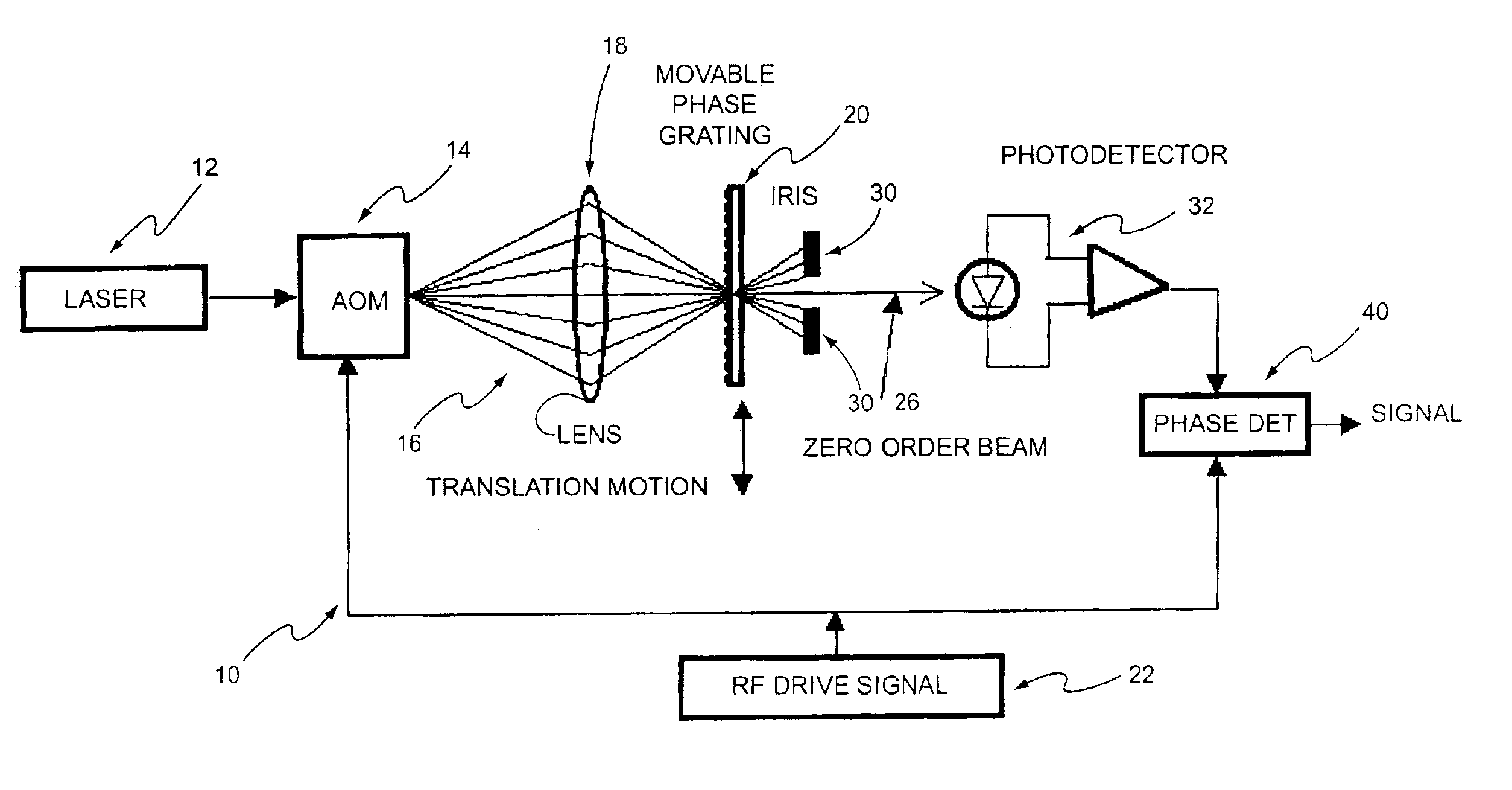
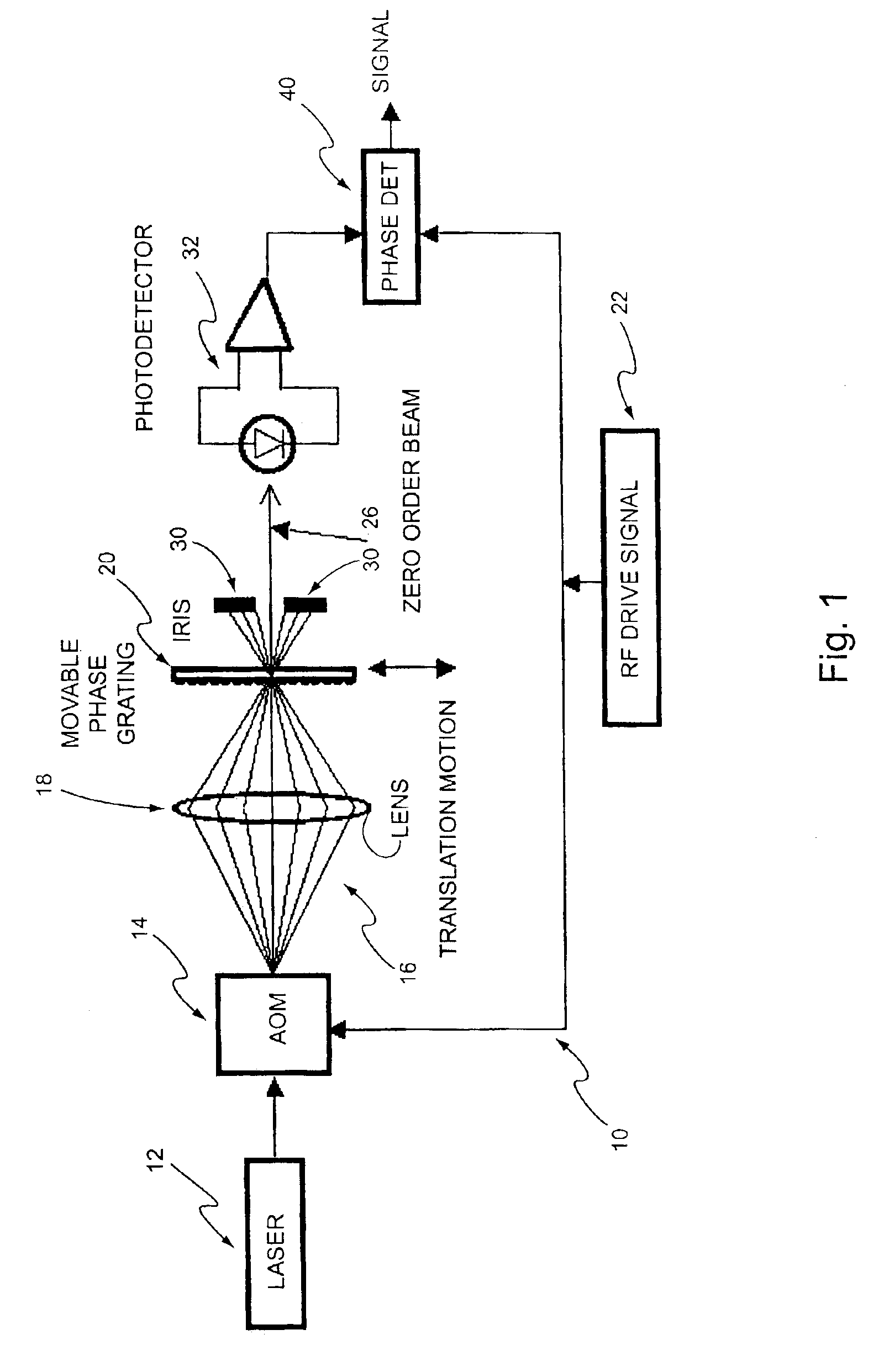
[0011]With reference to the diagram of FIG. 1, there is shown a heterodyne lateral grating interferometric encoder 10 of the present invention. The output from a laser 12 passes through an AOM 14 which can be considered as a traveling phase grating. The traveling phase grating in the AOM produces several diffracted order beams 16. A lens system 18 reimages the beams from the AOM onto a stationary phase grating 20. In accordance with this embodiment, the stationary phase grating may have a spatial frequency to match the spatial frequency of the beams, and an optical phase modulation depth of approximately 1.2 radians.

[0012]The spatial frequency of the traveling phase grating is determined by the RF drive frequency of an RF driver 22 divided by the acoustic velocity of the AOM material. Therefore, the rate at which the traveling phase grating sweeps is determined by the RF drive frequency. The optical phase modulation depth is determined by the RF drive power which, in accordance with...


PUM


Abstract

A heterodyne lateral grating interferometer having a laser signal received by an AOM which generates several defracted order beams including a zero order beam and higher order beams. A lens system reimages the defracted order beams onto a stationary phase grating. An RF drive signal is received by the AOM such that the spatial frequency of the traveling phase grating of the AOM is responsive to the frequency of the RF drive signal, and the optical phase modulation depth of the traveling phase grating is responsive to the power of the RF drive signal. A phase detector determines the phase of the zero order beam from the stationary phase grating with respect to the phase of the RF drive signal.

Description

BACKGROUND OF THE INVENTION[0001]This invention relates to a heterodyne lateral grating interferometric encoder, and more particularly to such an encoder with improved modulation. Interferometers of this type are used in applications requiring relative angular measurements with submicroradian resolution and repeatability.[0002]There are a number of problems associated with such interferometers that the presents invention addresses. A heterodyne lateral grating interferometric encoder requires the generation of an optical beam containing a sweeping sinusoidal fringe field. A Mach-Zender interferometer with acousto-optic modulators (referred to as Bragg cells or AOMs) is typically used for this purpose. Such interferometers are comprised of multiple mirrors, AOMs, and beam splitters, and alignment of all these components is difficult.[0003]Moreover, each AOM produces a frequency shift on the first order diffracted output beam for use in the interferometer. However, much optical power ...

Claims


Application Information

Patent Timeline
Patent Type & Authority Patents(United States)
IPC IPC(8): G01B9/02
CPCG01B9/02G01B9/0201G01B2290/20G01B2290/30
Inventor MUENTER, STEVEN E.WIDEN, KENNETH C.
Owner THE BOEING CO
Why Eureka
Try Eureka