Reduction of laser speckle in photolithography by controlled disruption of spatial coherence of laser beam

a laser beam and spatial coherence technology, applied in the field of apparatus and process for reducing speckle exhibited by laser beams, can solve the problems of high spatial coherence, difficult to achieve achromatic imaging optics in these wavelength regions, and problems relating to speckle, so as to reduce laser beam speckle laser beam speckle reduction

Inactive Publication Date: 2005-05-24
COHERENT GMBH
View PDF7 Cites 49 Cited by
  • Summary
  • Abstract
  • Description
  • Claims
  • Application Information

AI Technical Summary

Benefits of technology

[0019]In accord with the above object, a first embodiment of a method for reducing speckle of a laser beam comprises the step of shifting a phase of a first portion of the laser beam relative to a second portion of the laser beam, such that a spatial coherence of the laser beam is disrupted while a temporal coherence of the laser beam is substantially unchanged.
[0020]Also in accord with the above object, a second embodiment of a method for reducing speckle of a laser beam comprises the step of scattering a first portion of the laser beam relative to a second portion of the laser beam, such that a spatial coherence of the laser beam is disrupted while a temporal coherence of the laser beam is substantially unchanged.
[0021]Further in accord with the above object, a first embodiment of an apparatus for reducing speckle of a laser beam comprises a DUV-VUV transparent substrate bearing a periodic optical coating over a first region, the optical coating causing a phase shift of light transmitted through the first region relative to light transmitted outside of the first region, such that the phase shift generates a desired mi...

Problems solved by technology

Because of the extremely small magnitude of these dimensional ranges and their size relative to the wavelength of the incident laser beam, achromatic imaging optics are difficult to achieve in these wavelength regions.
Unfortunately, high spatial coherence can create problems relating to speckle.
Beams exhibiting a high degree of spatial coherence are especially prone to exhibit speckle.
Speckle is detrimental to many laser applications because it causes uneven illumination of areas by the beam.
Speckle is thus a particularly serious problem in photolithography, where uneven beam illumination can result in non-uniform development of photoresist materials that define the microscopic feature size of active devices.
Due in part to concerns about speckle, stepper and scanne...

Method used


Image

  • Reduction of laser speckle in photolithography by controlled disruption of spatial coherence of laser beam
  • Reduction of laser speckle in photolithography by controlled disruption of spatial coherence of laser beam
  • Reduction of laser speckle in photolithography by controlled disruption of spatial coherence of laser beam

Examples


first embodiment

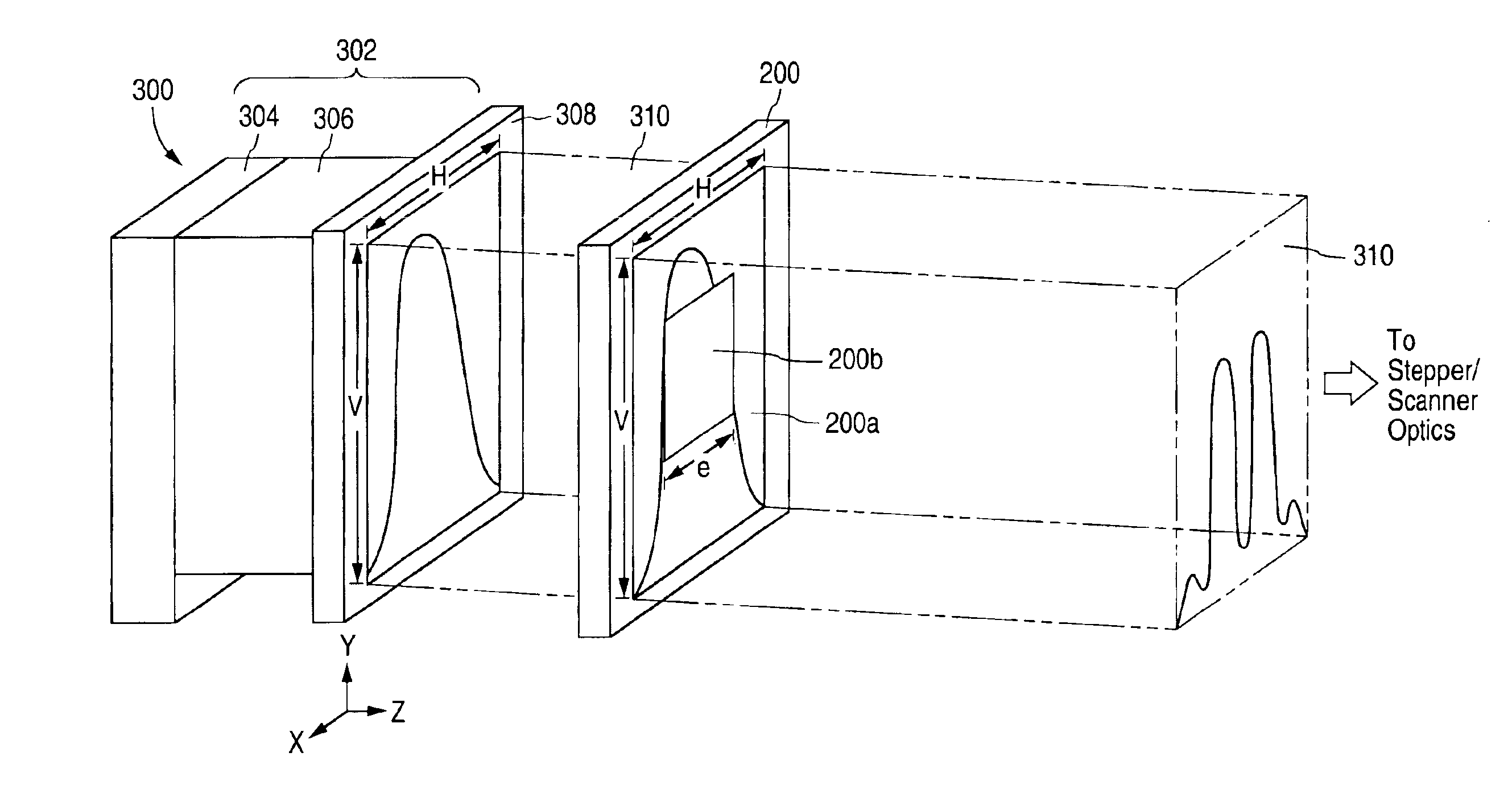
[0064]FIG. 3a shows a laser employing an anti-speckle apparatus in accordance with the present invention. Laser 300 includes resonator 302 including narrow band unit 304, discharge tube 306, and outcoupling mirror 308. Preferred gas mixtures and methods of stabilizing gas mixtures of these excimer lasers and other lasers such as the XeF, XeCl, KrCl excimer lasers, as well as the molecular fluorine laser, are described at: U.S. Pat. Nos. 4,393,505, 4,977,573 and 5,396,514, and U.S. patent applications Ser. Nos. 09 / 317,526, 09 / 418,052, 09 / 513,025, 60 / 137,907, 09 / 379,034, 60 / 160,126 and 60 / 124,785, each of which is assigned to the same assignee as the present application.

[0065]Laser beam 310 of fixed pulse length exits discharge tube 306 through an aperture having width H and height V, and passes through outcoupling mirror 308. At the time of passing through outcoupling mirror 308, beam 310 exhibits a high degree of spatial coherence in the x-y plane.

[0066]However, laser 300 further in...

embodiment 305

[0069]FIG. 3d shows a fourth laser embodiment 305 employing an anti-speckle apparatus 201 as an output coupler. In this way, the antispeckle apparatus 201 also has the reflectivity of a typical output coupler of an excimer or molecular fluorine laser and transmits the output beam 310. The plate 201 may be two plates such as produce etalonning in the system, as well. The plate may serves to dispersively line-narrow, such as being formed to disperse the beam as a prism or transmission grating or grism would, in addition to reducing the speckle and / or output coupling the beam. The fly eye lens 320 is shown in FIG. 3d, but may be taken out, as desired.

[0070]FIGS. 4A-4D show the calculated far field intensity distribution along the x-axis only, of beam 310 after it has passed through a anti-speckle apparatus 200 of FIG. 2 exhibiting a fixed phase shift of π and having center region 200b of various widths eH. Beam intensities are shown for phase retarding apparatuses where e varies from e...

third embodiment

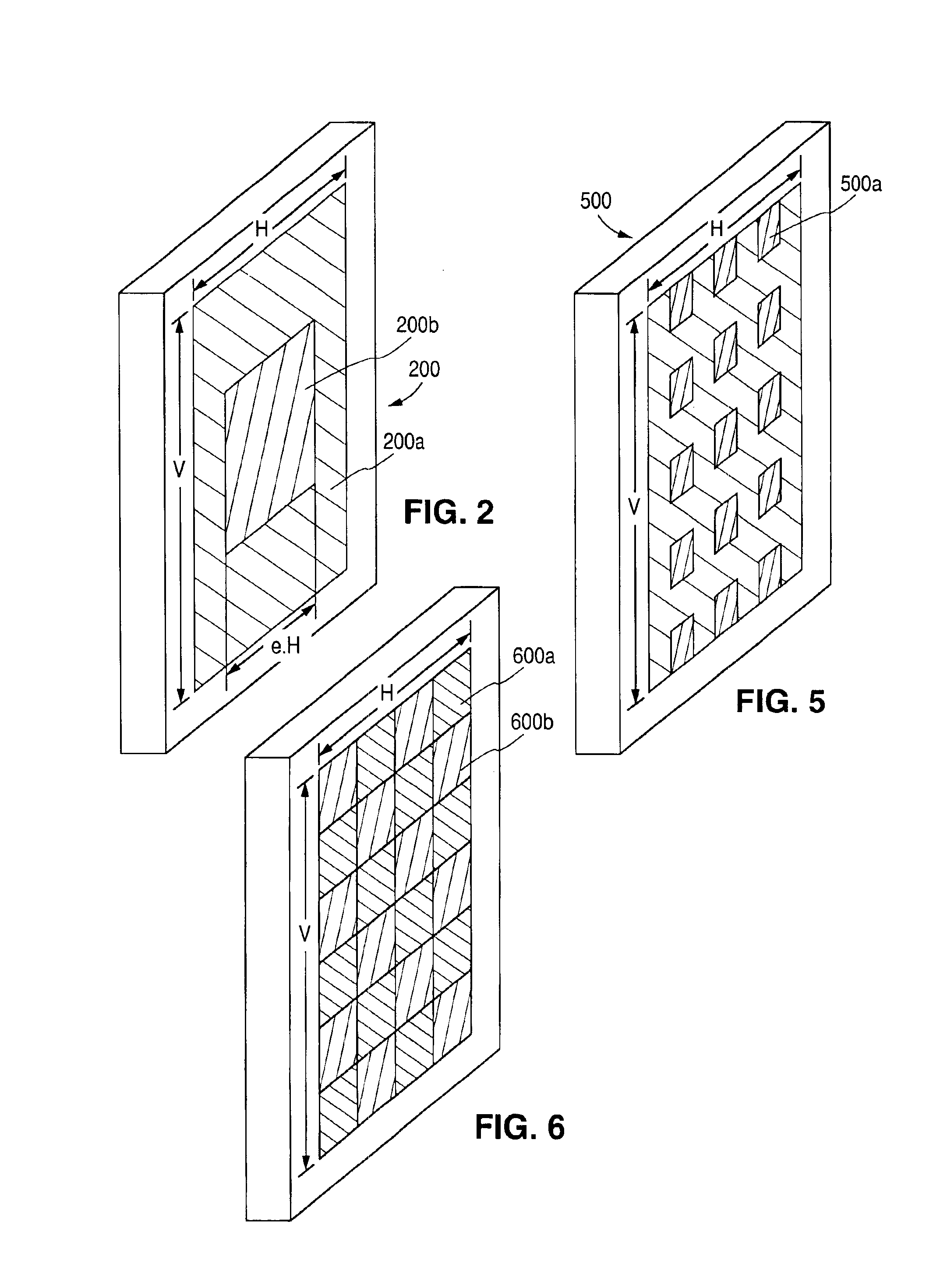
[0075]FIG. 6 shows an antispeckle apparatus in accordance with the present invention. Phase retarder plate 600 includes alternating regions 600a and 600b bearing different optical coatings that cause a relative shift in the phase of beam portions passing through these coated regions.

[0076]The embodiments of anti-speckle apparatuses described in conjunction with FIGS. 2, 5, and 6 are most advantageously used with a pulsed semi-narrow band excimer laser such as a KrF or ArF excimer laser having a characteristic bandwidth in excess of 200 pm, and an output beam narrowed to under 100 pm, typically using a dispersive prism. Other lasers such as the molecular fluorine laser could also benefit from the present invention.

[0077]In addition, these embodiments are most advantageously used in a photolithographic system including a catadioptric or all-reflective imaging system. Acceptable input laser emission bandwidths for catadioptric imaging systems are between about 15-100 pm at 248 nm, and ...


PUM


Abstract

Speckle of a laser beam is reduced by inserting an anti-speckle apparatus in the beam path to disrupt its spatial coherence while maintaining its temporal coherence. In one embodiment, the anti-speckle apparatus is a phase retarder plate bearing periodic optically-coated regions. Transmission or reflection of the beam through coated and uncoated regions causes an internal phase shift of first beam portions relative to second beam portions, thereby disrupting spatial coherence. Size and thickness of the coated regions can be carefully tailored to meet requirements of stepper and scanner equipment manufacturers for maximum allowable spatial coherence expressed as a minimum permissible number of coherent cells across the beam cross-section. An alternative embodiment of an anti-speckle apparatus is a scattering plate bearing a roughened surface. Transmission or reflection of the beam by the roughened surface disrupts the beam's spatial coherence. The correlation length and/or surface height of structures on the roughened surface of the scattering plate may be adjusted to achieve desired divergency and spatial coherence. A liquid matching medium or solid overcoating may be contacted with the roughened surface to adjust the index of refraction at the interface with the roughened surface. The anti-speckle apparatus may serve to outcouple the laser beam, as well, and a fly eye lens may be positioned after the anti-speckle appartus.

Description

PRIORITY[0001]This application claims the benefit of priority to United States Provisional Patent Application nos. 60 / 141,678 (filed Jun. 30, 1999) and 60 / 171,172 (filed Dec. 16, 1999).BACKGROUND OF THE INVENTION[0002]1. Field of the Invention[0003]The invention relates to an apparatus and process for reducing speckle exhibited by a laser beam, and particularly to insertion of an anti-speckle apparatus in the path of a laser beam in order to control the spatial coherence of the beam independent of the construction of the laser resonator.[0004]2. Discussion of the Related Art[0005]Radiation in the deep ultraviolet (DUV, λ>200 nm) and vacuum ultraviolet (VUV, λ<200 nm) is currently being applied in photolithography to fabricate integrated circuits. Specifically, the output of narrow band ArF and KrF excimer lasers (λ=193 nm, 248 nm) are utilized for making semiconductor devices having a feature size of between about 0.18 and 0.25 μm (produced by radiation from a KrF laser), or b...

Claims


Application Information

Patent Timeline
IPC IPC(8): G03F7/20H01L21/02H01L21/027H01S3/10G02B5/32G02B27/48H01S3/00H01S3/225
CPCG02B27/48H01S3/225G03F7/70583G02B5/32H01S3/005
Inventor KLEINSCHMIDT, JURGEN
Owner COHERENT GMBH
Why Eureka
Try Eureka