
High pressure pump system for supplying a cryogenic fluid from a storage tank

a cryogenic fluid and high pressure pump technology, which is applied in the direction of positive displacement liquid engines, machines/engines, containers, etc., can solve the problems of unsuitable trucks and buses, uneconomical and unpractical to build an lng tank with such a high operating pressure, and achieve a wide range of selectable flow rates

Inactive Publication Date: 2005-05-31
WESTPORT POWER
View PDF37 Cites 69 Cited by
  • Summary
  • Abstract
  • Description
  • Claims
  • Application Information

AI Technical Summary

Benefits of technology

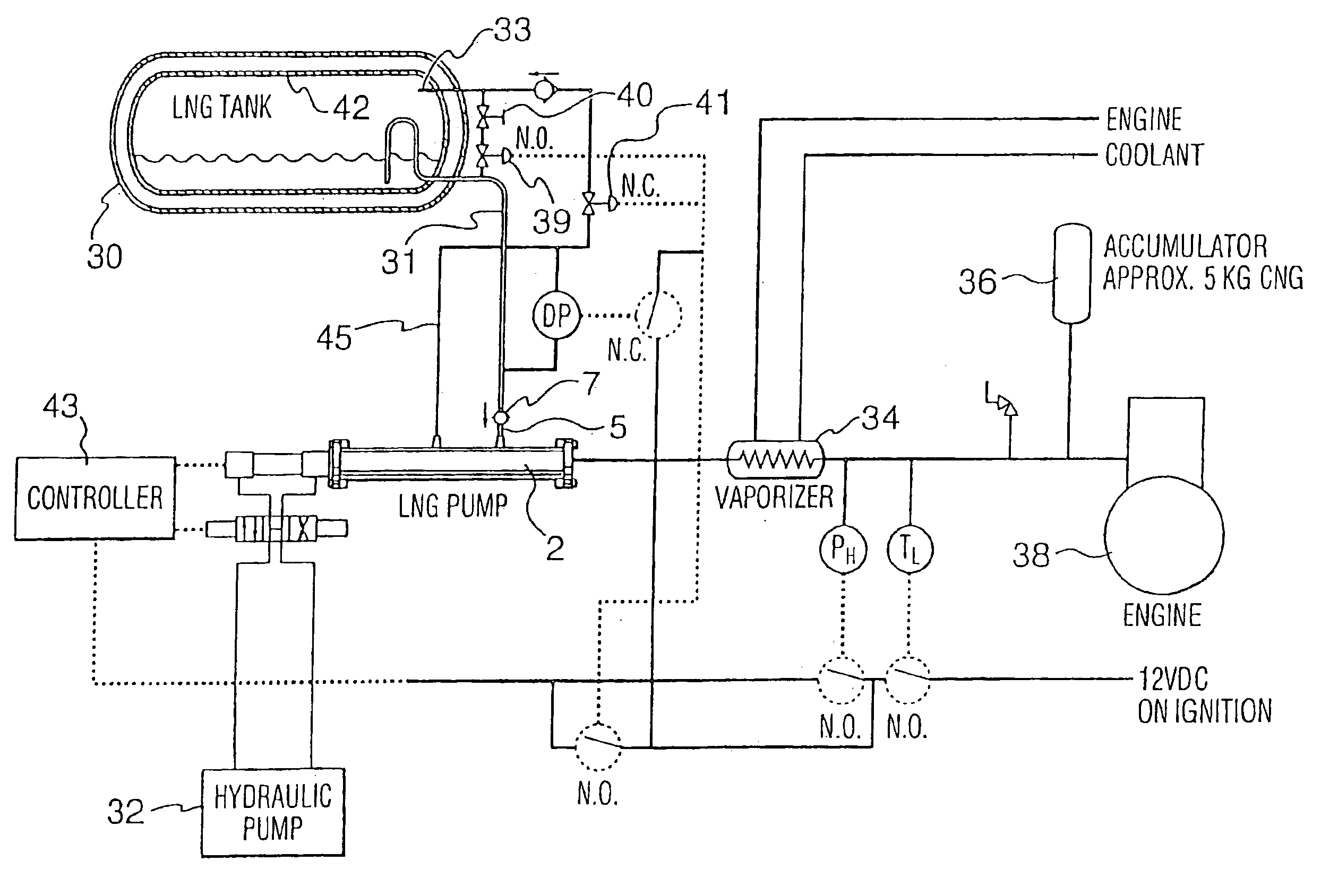
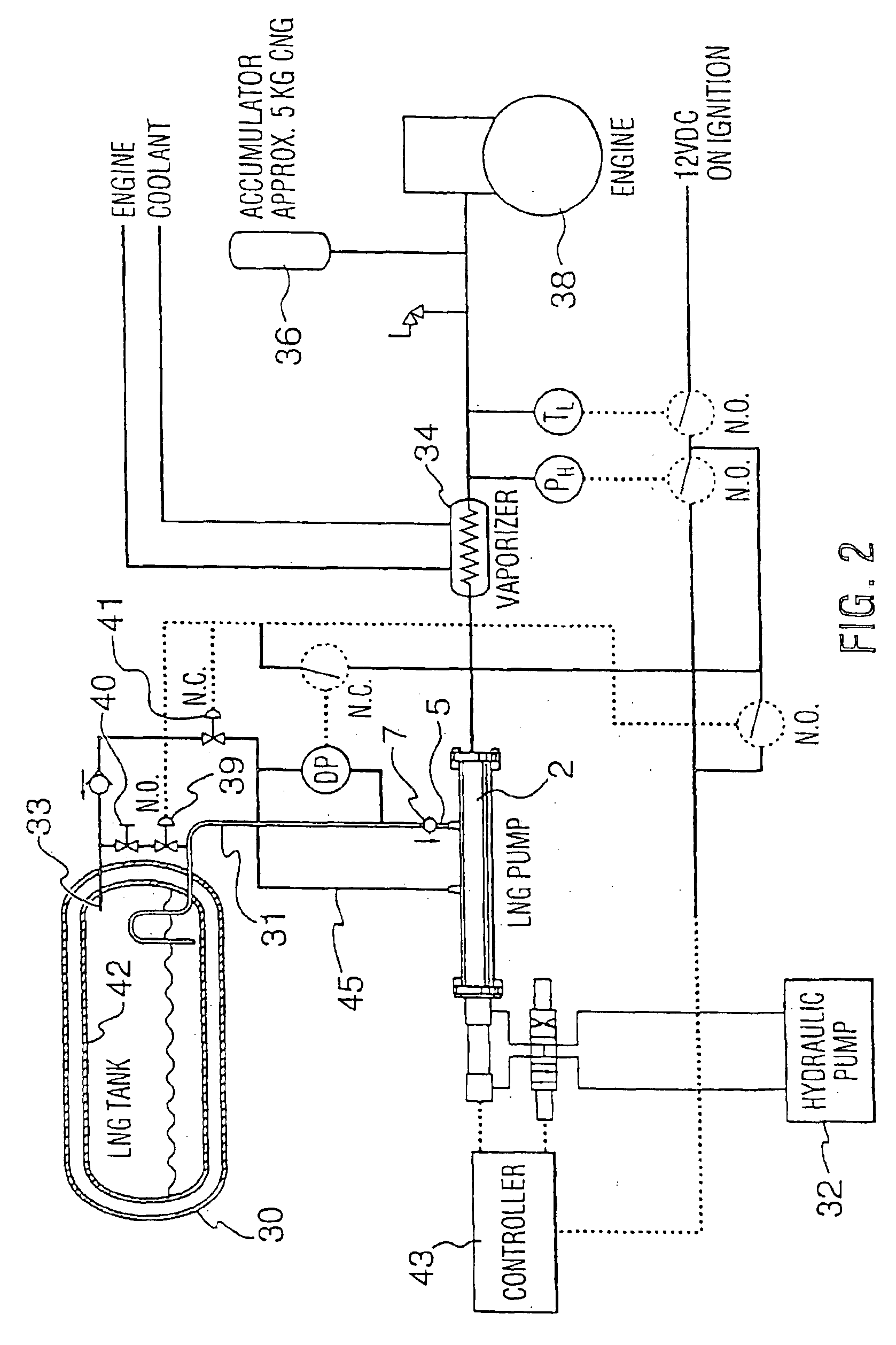
[0018]Because it is advantageous to store some gaseous fuels under cryogenic conditions, the method may be employed to pump a cryogenically stored fuel to an internal combustion engine. To provide a steady supply of high pressure fuel to an engine the method may comprise delivering fuel from the pump to an accumulator vessel and selecting an operating mode to control mass flow rate to maintain pressure within a predetermined range within the accumulator vessel. The volume of the fuel conduits and manifolds between the pump and engine may be sized to have a volume such that these conduits and manifolds themselves act as the accumulator, obviating the need for an actual “vessel”. The pressure may be monitored within the fuel conduit or manifold downstream from the pump, or within an accumulator vessel, if employed. The mass flow rate supplied by the pump system is controllable to maintain the monitored pressure within a predetermined range to ensure sufficient pressure for supplying the fuel to the desired application, such as an internal combustion engine. The method may further comprise increasing the vapor fraction supplied to the pump when vapor pressure within the storage tank is higher than a predetermined value or when the monitored pressure downstream from the pump is above a predetermined set point. That is, the vapor fraction can be increased to reduce vapor pressure in the storage tank to reduce or prevent the need for venting, or to continue operation of the pump system at a lower mass flow rate when pressure downstream of the pump is above a predetermined set point.
[0028]Once the pump has been cooled to the normal operating temperature, a valve controlling the flow of cryogenic fluid back from the pump to the storage tank is closed. That is, once the pump is cooled to predetermined temperature at which the pump is operable to pump the cryogenic liquid and vapor in one of the first or second operating modes, vapor is prevented from returning to the tank.
[0035]In this second embodiment, excess cryogenic fluid induced into the pump is advantageously recycled from the second chamber to the first chamber, so that no vapor is returned from the pump to the storage tank during normal operation. This is an advantage over known systems that return excess cryogenic fluid to the storage tank since such systems introduce heat into the storage tank with the return of the excess fluid.
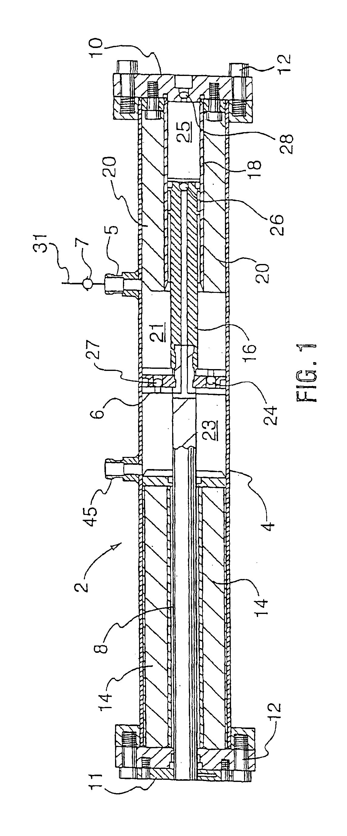
[0063]An advantage of one embodiment of the pump is that the pump may comprise a cold end disposed within a sump and a warm end opposite to the cold end, wherein the suction inlet is associated with the cold end and the discharge outlet is associated with the warm end. This arrangement prevents heat generated from the compression process from being transferred from the discharged cryogenic fluid to the cryogenic fluid being induced into the pump from the sump.
[0064]The system preferably further comprises a linear hydraulic drive connected to a piston of the pump. The linear hydraulic drive permits the piston to be drivable at a constant speed, which helps to reduce the creation of pressure pulses in the discharge pipe. In another embodiment, the pump speed may be changed to provide an additional means for influence the mass flow rate through the system to provide a greater range of selectable flow rates. However, this requires additional controls and apparatus for varying the speed of the hydraulic drive and the pump. The pump is preferably operable by the linear hydraulic drive at a fixed speed or at variable speeds, between 5 and 30 cycles per minute.

Problems solved by technology

Compressed natural gas (CNG) is commonly stored at ambient temperatures at pressures up to 3600 pounds per square inch (24,925 kPa), and is unsuitable for trucks and buses due to the limited operating range and heavy weight of the CNG storage tanks.
This makes it impossible to deliver the fuel directly from a conventional LNG vehicle tank and it is impractical and uneconomical to build an LNG tank with such a high operating pressure.
Equally, it is impossible to deliver the natural gas fuel directly from a conventional CNG tank as the pressure in such a tank is lower than the injection pressure as soon as a small amount of fuel has been withdrawn from the CNG tank.
High pressure cryogenic pumps have been on the market for many years, but it has proven difficult to adapt these pumps to the size and demand of a vehicle pump.
The problem with this approach is that it introduces a large heat leak into the LNG storage tank and consequently reduces the holding time of the tank.
The excess LNG which is drawn into such a chamber, over that which can fill a second chamber, is returned to the LNG tank and again, additional heat is introduced into the LNG, which is undesirable.
Another problem with a pumped LNG supply is that it is difficult to remove vapor from the LNG storage tank.
Extending the holding time cannot be done with conventional LNG pump systems that draw from the liquid phase only and cannot remove vapor.
In a stationary system, the positive feed pressure is typically attained by locating the pump several feet, for example, 5-10 feet (about 2-3 meters) below the lowest level of the liquid within the tank, and such installations are usually very costly.
Also, centrifugal pumps cannot easily generate high discharge pressures to properly inject fuel directly into the cylinder of an internal combustion engine and that are also desirable to reduce fuelling time for fuelling station applications.
In addition, the relatively small displacement of these pumps results in relatively small inlet valves which, when opened, tend to unduly restrict flow through the valves.
Large cryogenic piston pumps, with a capacity of about 40 gallons per minute (150 liters per minute) have been built, but such pumps are designed for very high pressure delivery, require a positive feed pressure and are extremely costly.

Method used


Image

  • High pressure pump system for supplying a cryogenic fluid from a storage tank
  • High pressure pump system for supplying a cryogenic fluid from a storage tank
  • High pressure pump system for supplying a cryogenic fluid from a storage tank

Examples


second embodiment

[0090]FIG. 4 illustrates a detailed enlarged section view of the present system, in which LNG pump 48 is built into LNG tank assembly 30. FIG. 4 illustrates suction line 31 in looped configuration to thereby provide a gas trap, as is common in the cryogenic and LNG art. Pump 48 is held in place against seal 47 formed in the end of sump 46 by bolts or some similar holding mechanism. Pump 48 can be separated from seal 47 and withdrawn by removing the securing bolts. The LNG from inner tank 42 (see FIG. 3) flows through suction line 31 into space 49 between sump 46 and the outer shell of pump 48. The vacuum within sump space 44 (see FIG. 3) is maintained by sump space 44 being sealed by the exterior of sump 46 and sleeve 50. Pump 48 can be withdrawn from the interior of sleeve 50 without disturbing the vacuum in space 44 (see FIG. 6). Sump 46 is sealed to sleeve 50 at junction 52.

[0091]Built-in pump 48 operates in the following manner. When piston 54 retracts to the left, LNG is drawn ...

third embodiment

[0093]The pump shown in FIG. 4 will pump LNG to high pressure without inducing heat into storage tank assembly 30, but if operating conditions are such that a longer holding time is demanded, an inducer feature similar to that shown in FIGS. 1 and 2 can be added. FIG. 5 illustrates a detailed enlarged section view of the present system, which features an LNG pump built into the LNG tank in association with an inducer. It will be understood that FIG. 5 is illustrative only and would not be built precisely as shown. The narrow left end of sump 46 would have to be layered in order to enable the inducer of pump 148 to be withdrawn.

[0094]In the embodiment illustrated in FIG. 5, induction chamber 68 is attached to the inlet end of pump 148 thereby combining some of the novel features of pump 2 and pump 48. The volume of induction chamber 68 is on the order of four times larger than chamber 51, that is, the diameter of chamber 68 is twice that of chamber 51. A smaller piston rod 59 is exte...


PUM


Abstract

A medium and high pressure pump systems supplies a cryogenic fluid from a storage tank. The system comprises a pump that is operable to pump cryogenic liquid or a mixture of cryogenic liquid and vapor. The pump preferably comprises an inducer with at least two chambers and means for recycling excess fluid within the inducer instead of returning excess fluid to the storage tank. The reciprocating pump is preferably double acting such that fluid is discharged from the pump during both extension and retraction strokes.

Description

RELATED APPLICATIONS[0001]This application is a continuation of U.S. patent application Ser. No. 09 / 972,521, field Oct. 5, 2001 now U.S. Pat. No. 6,659,730, of the same title, which is a continuation-in-part of U.S. patent application Ser. No. 09 / 530,628 filed May 2, 2000, entitled “High Pressure Fuel Supply System for Natural Gas Vehicles”, now abandoned. The '628 application related to and claimed priority benefits from U.S. patent application Ser. No. 08 / 965,969 of the same title, now U.S. Pat. No. 5,884,488. The '521 and '628 applications and the '969 patent are hereby incorporated by reference in their entirety.FIELD OF THE INVENTION[0002]This invention relates to medium and high pressure pump systems for supplying a cryogenic fluid from a storage tank. A particularly advantageous application for the system and methods is for supplying a cryogenically stored fuel to an internal combustion engine.BACKGROUND OF THE INVENTION[0003]Natural gas has been used as a fuel for piston eng...

Claims


Application Information

Patent Timeline
Patent Type & Authority Patents(United States)
IPC IPC(8): F04B25/00F04B25/02F04B15/08F04B19/06F04B15/00F04B19/00F02M37/00F02M37/12F04B23/02F04B49/00
CPCF04B15/08F04B25/02F04B19/06Y10S417/901Y02T10/30
Inventor GRAM, ANKERNOBLE, STEPHEN DUNCAN
Owner WESTPORT POWER
Learn More