Method and apparatus for seismic stimulation of fluid-bearing formations

a fluid-bearing formation and seismic stimulation technology, which is applied in seismic energy generation, borehole/well accessories, construction, etc., can solve the problems of destroying the bottom of the well, reducing the power of elastic waves, and expensive data analysis, so as to reduce the volume of the compression chamber

Inactive Publication Date: 2005-05-31
APPLIED SEISMIC RES CORP
View PDF5 Cites 28 Cited by
  • Summary
  • Abstract
  • Description
  • Claims
  • Application Information

AI Technical Summary

Benefits of technology

[0015]Accordingly, a primary object of a first embodiment of the present invention is to provide an apparatus for producing a shock wave in a borehole, such as a well, which includes a pumping unit arranged at the wellhead, a tubing string extending downwardly into the production casing of the well, a hollow cylinder assembly connected with the bottom of the tubing string, and a pair of plungers arranged within the cylinder assembly and connected with the pumping unit with sucker rods and a polish rod for compressing liquid contained within the cylinder assembly and discharging the compressed liquid into the production casing, thereby generating a shock wave. The cylinder assembly includes a hollow upper cylinder, a hollow lower cylinder arranged below the upper cylinder, a crossover cylinder arranged between the upper and lower cylinders, and a compression cylinder containing a compression chamber arranged between the crossover cylinder and the upper cylinder. The lower cylinder has a larger inner diameter than the upper cylinder and the lower plunger has a larger diameter than the upper plunger. In addition, the internal bore of the lower cylinder is adapted to receive the lower plunger, and the internal bore of the upper cylinder is adapted to receive the upper plunger. When the plungers are displaced upwardly in the cylinder assembly, the lower plunger travels into the compression chamber and the upper plunger travels out of the compression chamber. Due to the lower plunger having a greater diameter than the upper plunger, the volume of the compression chamber is reduced and the liquid contained therein becomes compressed. When the pumping unit reaches the top of its stroke, the lower plunger allows the compressed liquid contained in the compression chamber to be discharged into the well.

Problems solved by technology

Problems have been encountered because of the lack of compatibility of surveys performed at various times. Analysis of the data is expensive and often unreliable.
However, the repeated impact of the weight eventually destroys the bottom of the well.
The amount of damage can be minimized by limiting the impact force applied to the anvil plate, but this lowers the power of the elastic waves which reduces efficiency.
In addition, the efficiency of this method is limited by a low energy transfer coefficient of the potential energy of the weight into the energy of the elastic waves.
Although this method achieves higher efficiency than the method described in the Russian Patent No. 1,710,709 discussed above, it is limited in terms of its reliability, effectiveness and efficiency because (1) a cement / bridge plug must be installed to pressurize the borehole, (2) the pressure on the front of the shock wave must be limited due to the low reliability of the stuffing box undergoing a high periodic pressure, (3) additional surface equipment must be used to compensate for liquid leaking through the stuffing box, casing, cement plug, and other equipment, and (4) it is unable to generate a shock wave near the bottom hole for wells having a depth of greater than 800-1000 feet.

Method used


Image

  • Method and apparatus for seismic stimulation of fluid-bearing formations
  • Method and apparatus for seismic stimulation of fluid-bearing formations
  • Method and apparatus for seismic stimulation of fluid-bearing formations

Examples


Embodiment Construction

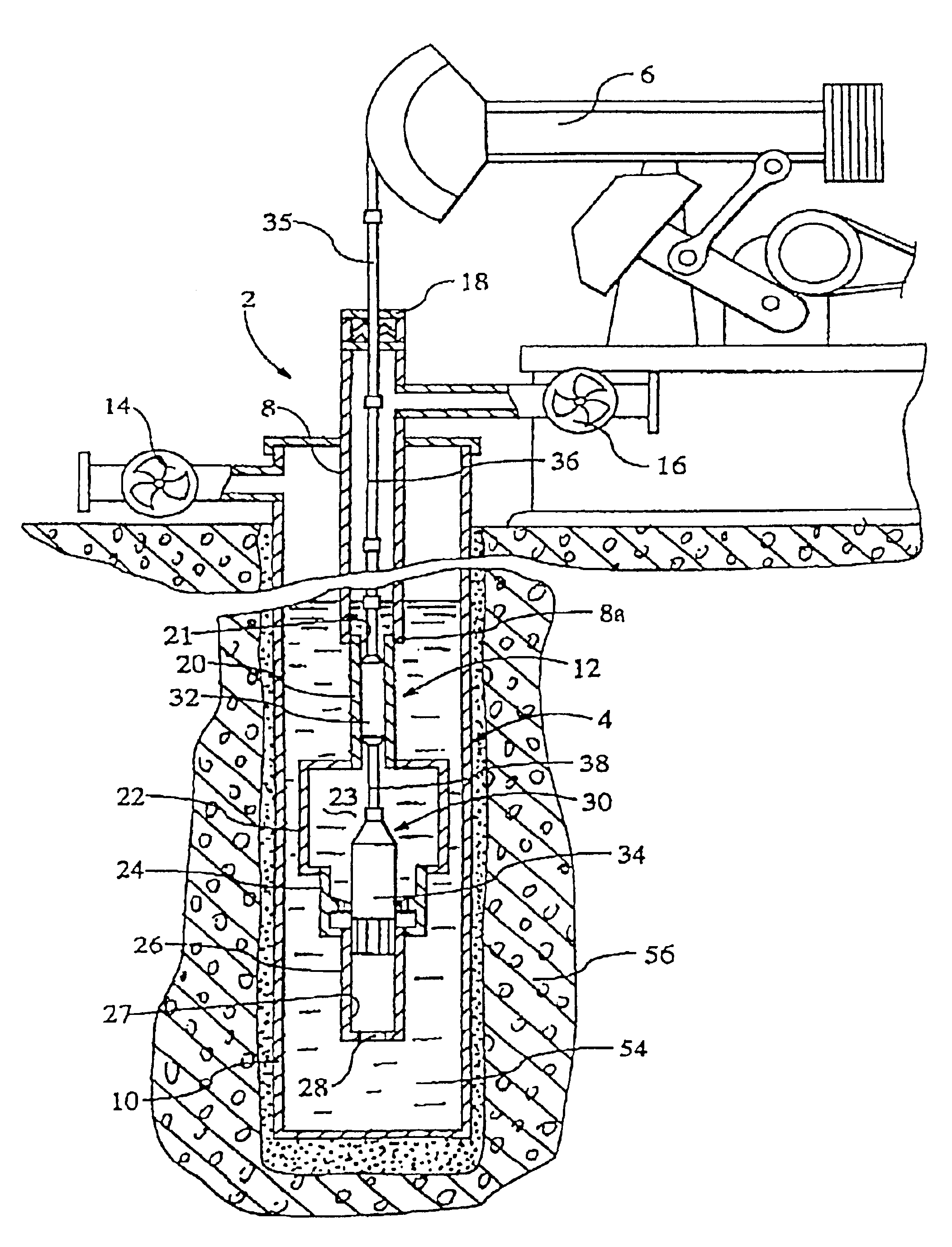
[0042]Referring first to FIG. 1, there is shown a device 2 for producing a shock wave in a borehole or well 4. The device includes a pumping unit 6 arranged at the wellhead, a tubing string 8 extending downwardly into the perforated production casing 10 of the well, and a cylinder assembly 12 connected with the lower end 8a of the tubing string. A casing valve 14, a tubing valve 16, and a stuffing box 18 are also arranged at the wellhead.

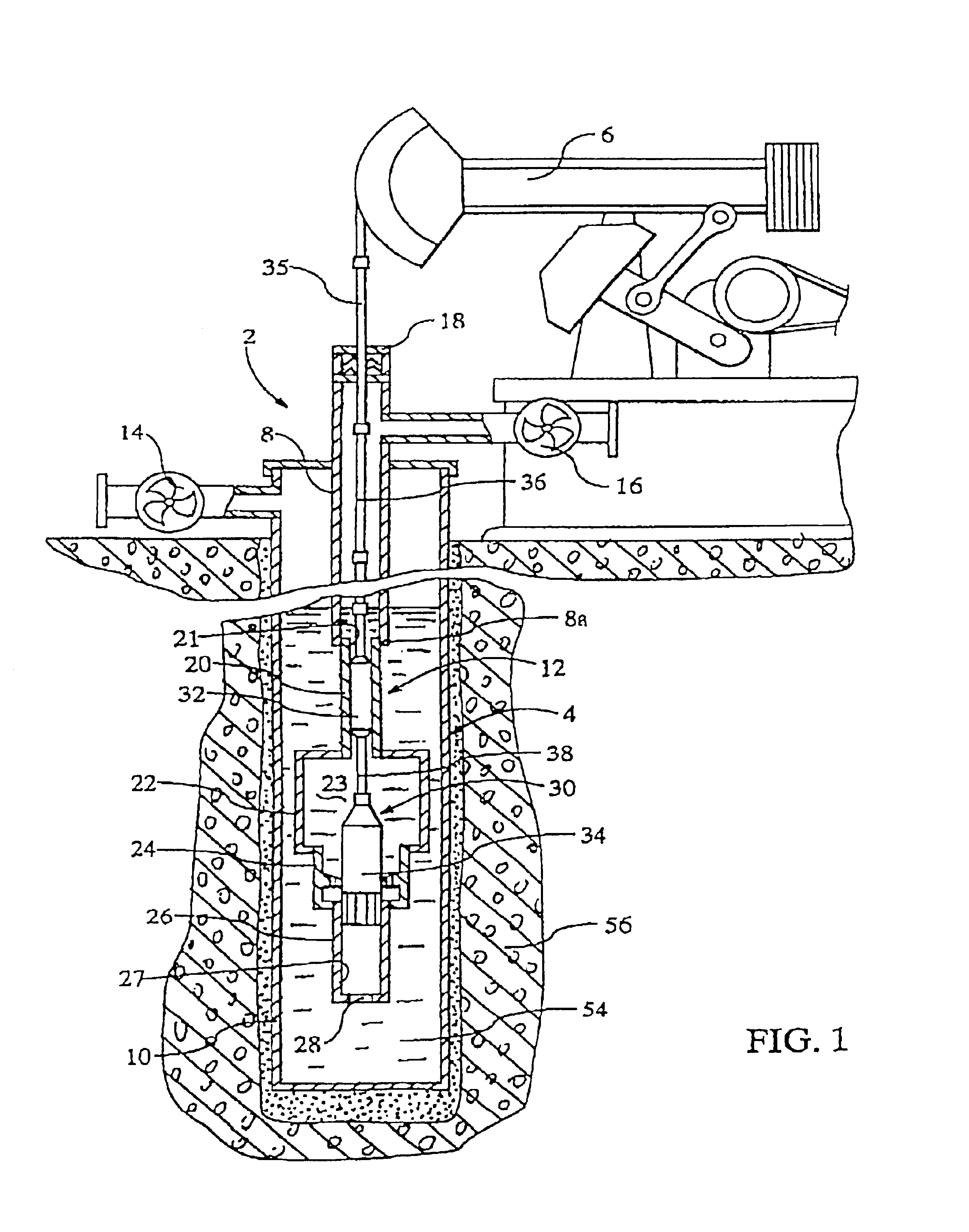
[0043]The cylinder assembly 12 includes an upper cylinder 20 connected with the lower end of the tubing string 8a, a compression cylinder 22 connected with the lower end of the upper cylinder 20, a crossover cylinder 24 connected with the bottom of the compression cylinder 22, and a lower cylinder 26 connected with the bottom of the crossover cylinder 24. The upper cylinder contains an internal bore 21, the compression cylinder contains a compression chamber 23, and the lower cylinder contains an internal bore 27, and an opening 28 in its lower end....


PUM


Abstract

An apparatus and seismic method for producing an shock wave in an oil well borehole, with a pumping unit arranged at the wellhead, a tubing string extending downward into the production casing of the well, a hollow cylinder assembly connected with the bottom of the tube string, and pair of plungers arranged within the cylinder assembly and connected with the pumping unit with sucker rods and a polish rod for compressing liquid contained within the cylinder assembly and discharging the compressed liquid into the production casing, thereby generating a shock wave. The cylinder assembly includes an upper cylinder, a lower cylinder below the upper cylinder, a crossover cylinder below the upper and lower cylinders, and a compression chamber cylinder containing a compression chamber arranged between the crossover cylinder and the upper cylinder. The lower cylinder is adapted to receive the lower plunger, and the upper cylinder is adapted to receive the upper plunger. The lower plunger has a larger diameter than the upper plunger, and the plunger movement effects the volume of the compression chamber by reduction, the liquid contained therein becomes compressed and is discharged on the down stroke into the well. In addition, remote seismic data is collected and processed from remote well locations.

Description

CROSS REFERENCE TO RELATED APPLICATIONS[0001]This application is a continuation of PCT application No. PCT / US99 / 28060, dated Nov. 23, 1999, which is a continuation-in-part of U.S. Ser. No. 08 / 927,032, dated Sep. 10, 1997, issued Jan. 18, 2000 as U.S. Pat. No. 6,015,010.TECHNICAL FIELD[0002]The present invention relates to a shock wave generating method and device and, more particularly, to a method and device for repeatedly generating shock waves in an injection well borehole to increase oil recovery and oil production and to carry out the continuous seismic survey of oil an bearing formation.BACKGROUND OF INVENTION[0003]Seismic surveys, taken at different stages in the life of an oil field, are used to locate pockets of hydrocarbons. These types of surveys are generally referred to as 4-D seismic surveys which incorporate data relating to depth, width, length and time. Problems have been encountered because of the lack of compatibility of surveys performed at various times. Analysi...

Claims


Application Information

Patent Timeline
Patent Type & Authority Patents(United States)
IPC IPC(8): E21B43/00E21B43/12G01V1/02G01V1/52G01V1/40E21B28/00
CPCE21B43/003G01V1/52G01V1/02E21B43/127E21B28/00
Inventor KOSTROV, SERGEY A.WOODEN, WILLIAM O.
Owner APPLIED SEISMIC RES CORP
Why Eureka
Try Eureka