Method and apparatus for growing single crystal

a single crystal and growing method technology, applied in the direction of crystal growth process, polycrystalline material growth, under protective fluid, etc., can solve the problem of limited crystal growth rate, inability to obtain products having a constant diameter, and high rate of single crystal growth. achieve the effect of increasing the crystal growth ra

Inactive Publication Date: 2005-05-31
SHIN-ETSU HANDOTAI CO LTD
View PDF8 Cites 18 Cited by
  • Summary
  • Abstract
  • Description
  • Claims
  • Application Information

AI Technical Summary

Benefits of technology

[0013]The present invention was accomplished in view of the aforementioned problem, and an object of the present invention is to provide a method for growing a single crystal and apparatus for growing a single crystal that can exert cooling effect on a growing single crystal to the maximum extent so as to realize higher crystal growth rate, even when a silicon single crystal having a diameter of 300 mm or more is grown.

Problems solved by technology

At this time, the pulling rate for a portion having a constant diameter of the single crystal ingot is usually extremely slow, i.e., about 0.5 to 1 mm / min, and if it is pulled fast by constraint, there are arisen various problems.
For example, the growing single crystal is deformed and thus a cylindrical product having a constant diameter can no longer be obtained, slip dislocations are generated in the single crystal ingot, the crystal is detached from the melt and thus it cannot be a product and so forth.
Therefore, increase of the crystal growth rate is limited.
However, if fluid such as water generally used as the cooling medium become close to the melt surface heated to a high temperature exceeding 1000° C., it may be a cause of phreatic explosion and thus dangerous.
Thus, it has become clear that cooling of the crystals become insufficient even when such cooling structures as mentioned above are used and thus it is difficult to use further higher crystal growth rate, so that decrease of productivity of crystals is invited.
That is, it was found that there was a problem as described below.
However, a restriction is imposed on the apparatus that a cooling duct for circulating a liquid refrigerant for cooling the cooling member must be sufficiently separated from the melt surface so that it should not be brought into contact with the melt surface when the crucible containing the melt is elevated to the maximum height that the crucible can reach, due to the problem concerning the safety described above.
Therefore, there is caused a problem that the cooling effect provided by the cooling medium is unlikely to reach the end of the cooling member.

Method used


Image

  • Method and apparatus for growing single crystal
  • Method and apparatus for growing single crystal
  • Method and apparatus for growing single crystal

Examples


experiment 1

(Experiment 1)

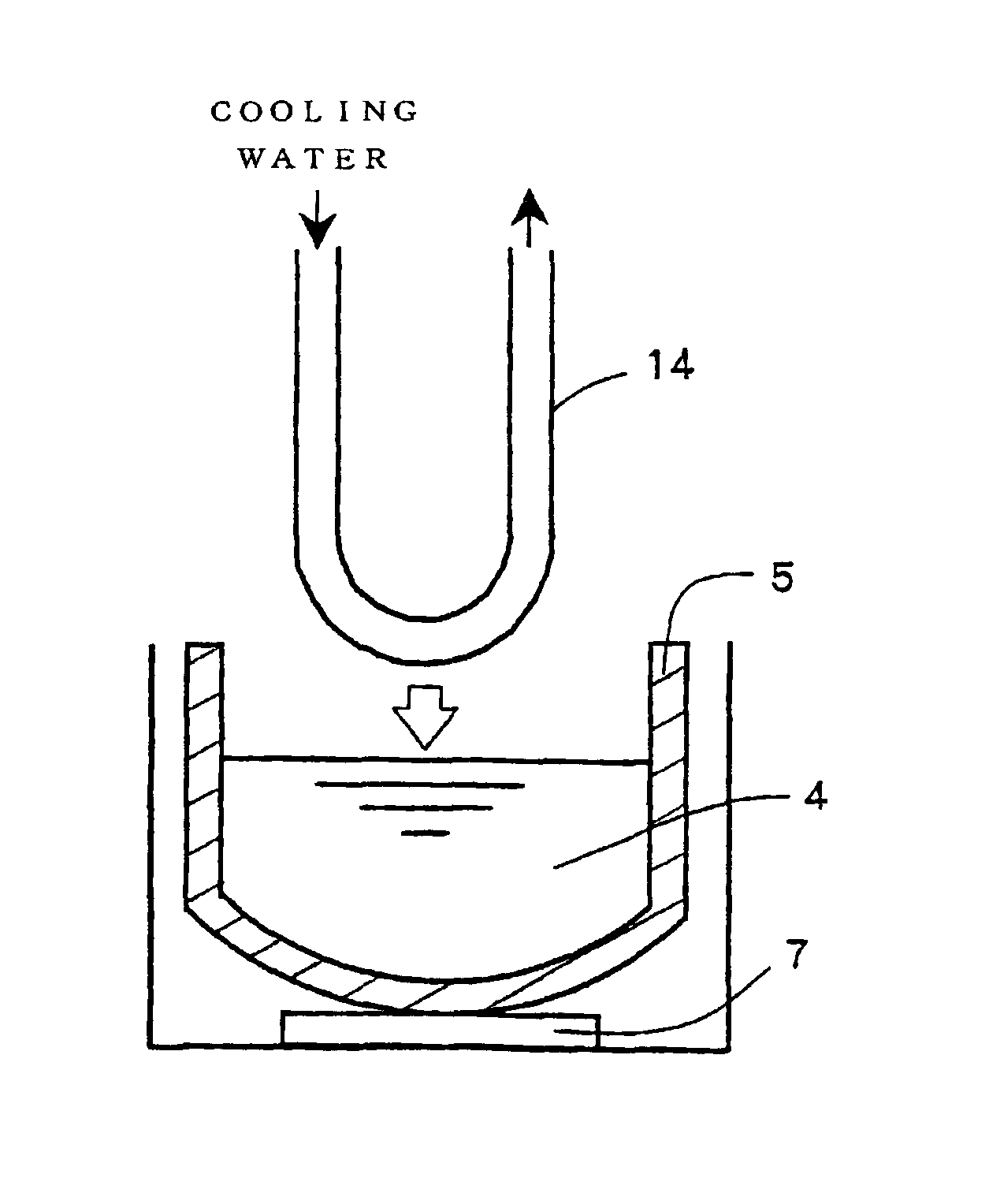
[0036]A U-shaped copper pipe 14 (outer diameter: 8 mm, wall thickness: 0.8 mm) and a small size quartz crucible 5 (inner diameter: 48 mm, provided with a heater at bottom) as shown in FIG. 3 were prepared.

[0037]First, in consideration of safety, a preliminary experiment was performed by using SiGe (Si: 1 weight %, solidification point: about 1050° C.), which had a melting point lower than that of silicon, as the melt raw material. An amount of 200 g of this SiGe was introduced into the quartz crucible 5, and the raw material was melt with maintaining the temperature of the heater 7 at the bottom of the crucible 5 at 1222° C. Water was flown (4.7 L / min) in the U-shaped copper pipe 14, and the water-cooled copper pipe 14 was immersed into the raw material melt 4. As a result, even if the water-cooled copper pipe 14 was brought into contact with the SiGe melt, it was not melted at all (melting point of copper: 1083° C.) and, to the contrary, there was observed a phenomeno...

experiment 2

(Experiment 2)

[0042]Then, in order to confirm effect of water cooling by a water-cooled copper pipe, a copper plate 15 (length: 50 mm, width: 20 mm, thickness: 2 mm) was welded at an end of a water-cooled copper pipe 14 the same as that of the experimental example 1 by using silver solder as shown in FIG. 4, and an experiment was performed in which the copper plate portion was immersed into a silicon melt. A thermocouple 21 was provided at the lower end of the copper plate 15 so as to enable temperature measurement.

[0043]The flow rate of cooling water was set to be 6.6 L / min, and the temperature of the silicon melt was adjusted to 1520° C., which was higher than the melting point by 100° C. In this state, the temperature of the lower end of the copper plate 15 located about 4 cm above the melt surface became 465° C. When the copper plate 15 was descended from the above position and brought into contact with the silicon melt 4, the contacting portion was heated slowly to redness and ...

example 1

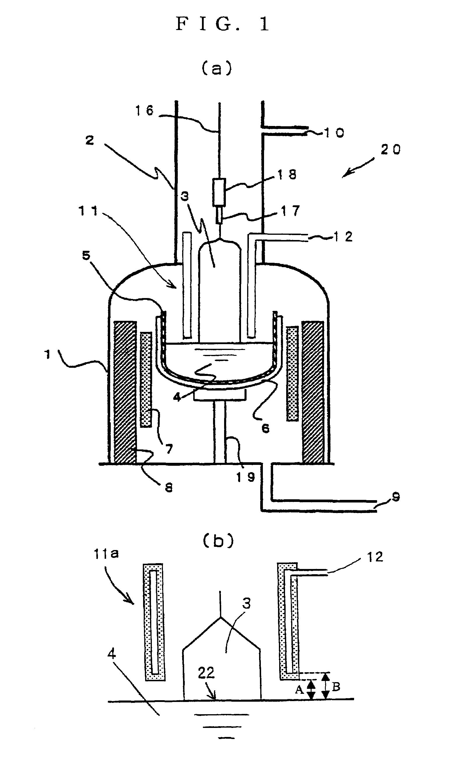
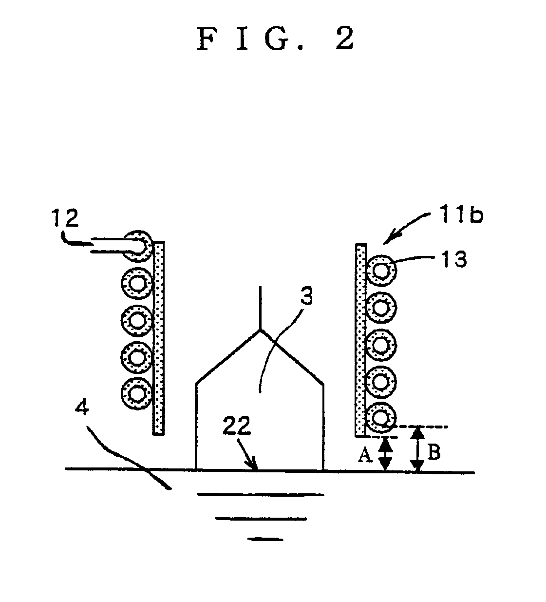
[0076]A silicon single crystal ingot was grown by the MCZ method using the apparatus 20 for growing a single crystal shown in FIG. 1 provided with an electromagnet (not shown in the drawing) outside the main chamber 1. The cooling cylinder 11 was a hollow cooling cylinder 11a, of which material was copper, and water was used as a cooling medium. The end of the cooling cylinder 11 was brought close to the melt surface so that the distance separating them should be 20 mm to perform the operation. On the other hand, a magnetic field was applied to the silicon melt 4 so that the magnetic field strength at the center of horizontal magnetic field should be 4000 G, and a hot zone that could contain a crucible having a diameter of 24 inches was used.

[0077]An amount of 150 kg of polycrystal silicon raw material was introduced into the crucible having a diameter of 24 inches, and a single crystal having a diameter of 8 inches (200 mm) and a length of constant diameter portion of about 100 cm ...


PUM

PropertyMeasurementUnit
diameteraaaaaaaaaa
temperatureaaaaaaaaaa
diameteraaaaaaaaaa

Abstract

The present invention provides a method and apparatus for growing a single crystal by the Czochralski method, wherein a single crystal is grown with forced cooling of neighborhood of a crystal growth interface by disposing a cooling cylinder formed of copper or a metal having a heat conductivity larger than that of copper at least in the vicinity of the crystal growth interface so as to surround the single crystal under pulling and circulating a cooling medium in the cooling cylinder. Thus, there are provided a method and apparatus for growing a single crystal, which can exert cooling effect on a growing single crystal to the maximum extent so as to realize higher crystal growth rate, even when a silicon single crystal having a diameter of 300 mm or more is grown.

Description

TECHNICAL FIELD[0001]The present invention relates to a method for growing a single crystal and apparatus for growing a single crystal used for production of single crystals such as silicon single crystals by the Czochralski method (also referred to as the “CZ method” or “pulling method” hereinafter).BACKGROUND ART[0002]Hereafter, conventional art relating to the present invention will be explained by exemplifying growing of a silicon single crystal.[0003]An apparatus for growing a single crystal used for producing a silicon single crystal by the CZ method generally comprises a crucible containing a raw material melt, which can be moved upwardly and downwardly, and a heater disposed so as to surround the crucible, both of which are provided in a main chamber for growing a single crystal, and a pulling chamber for containing and taking out a grown single crystal is continuously provided above the main chamber. When a single crystal is produced by using such an apparatus for growing a...

Claims


Application Information

Patent Timeline
Patent Type & Authority Patents(United States)
IPC IPC(8): C30B15/14C30B15/00C30B29/06H01L21/208
CPCC30B15/14C30B29/06Y10T117/1068Y10T117/1072Y10T117/1032C30B15/00
Inventor ABE, TAKAOYAMADA, TORU
Owner SHIN-ETSU HANDOTAI CO LTD
Why Eureka
Try Eureka