High power modulator

a high-power modulator and high-voltage technology, applied in electromagnetic wave modulation, pulse technique, instruments, etc., can solve the problems of physical largeness, cost, size and configuration challenges, etc., and achieve the effect of simple modulator design, cost-effectiveness and higher reliability

Inactive Publication Date: 2005-05-31
DIVERSIFIED TECH INC
View PDF28 Cites 31 Cited by
  • Summary
  • Abstract
  • Description
  • Claims
  • Application Information

AI Technical Summary

Benefits of technology

[0005]The present invention relates to a high power modulator that uses semiconductor devices as a cost-effective alternative to high voltage tubes. Using solid state semiconductor devices results in a simpler modulator design with higher reliability, higher efficiency, and lower cost. Solid state devices are generally

Problems solved by technology

For some applications, however, the apparatus described in the '610 patent may be physically large and expensive to manufacture.
F

Method used


Image

  • High power modulator
  • High power modulator
  • High power modulator

Examples


Embodiment Construction

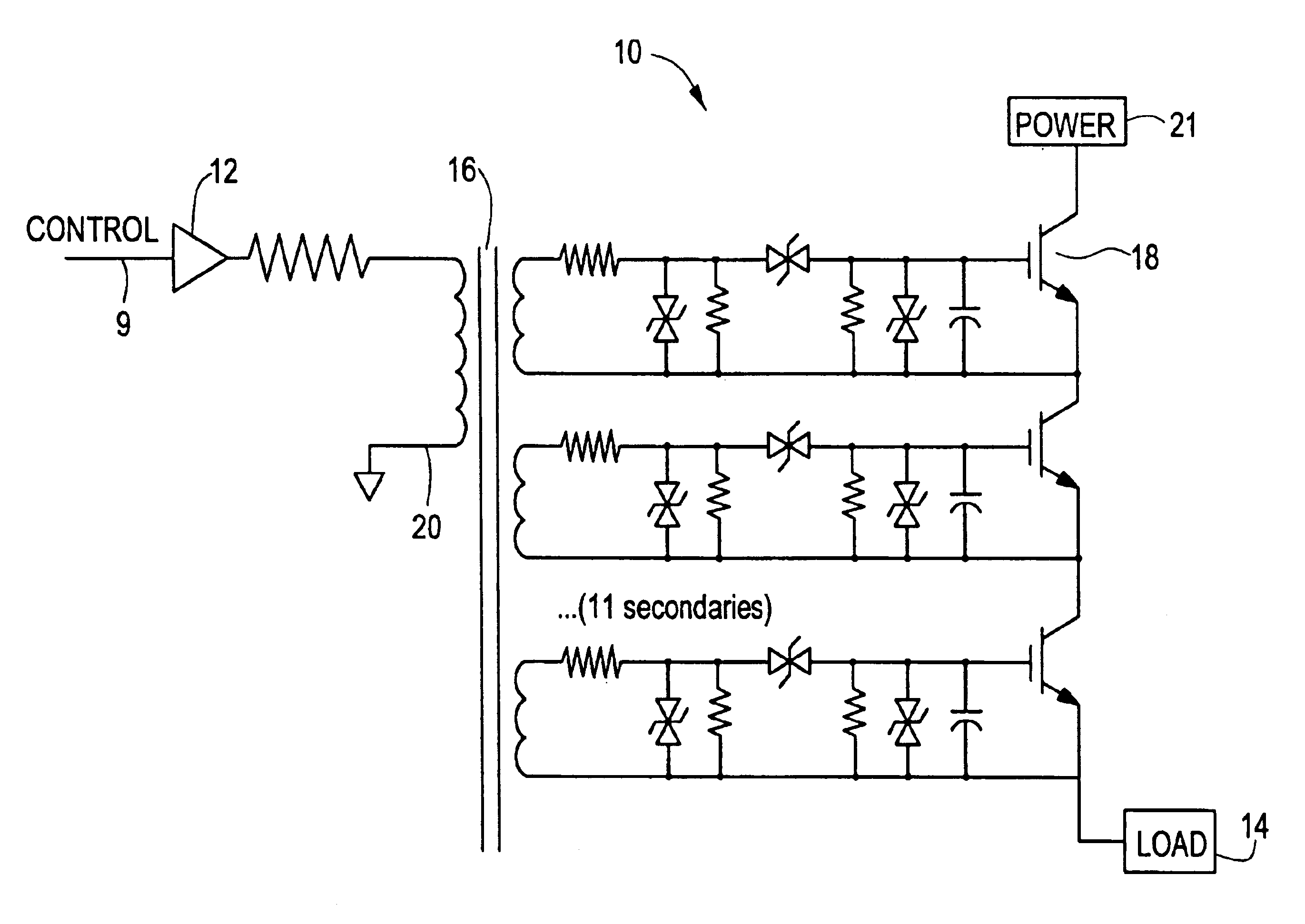
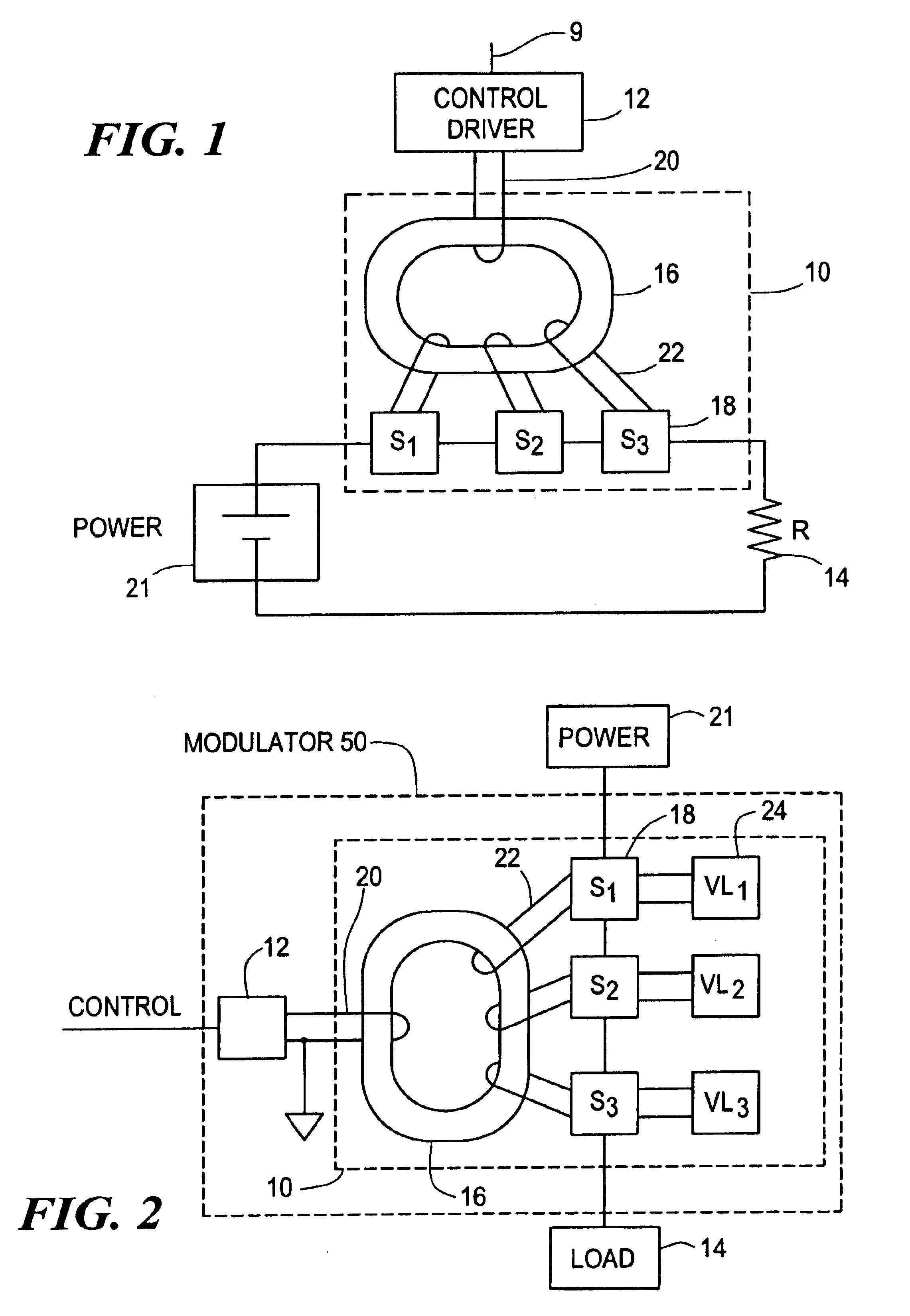
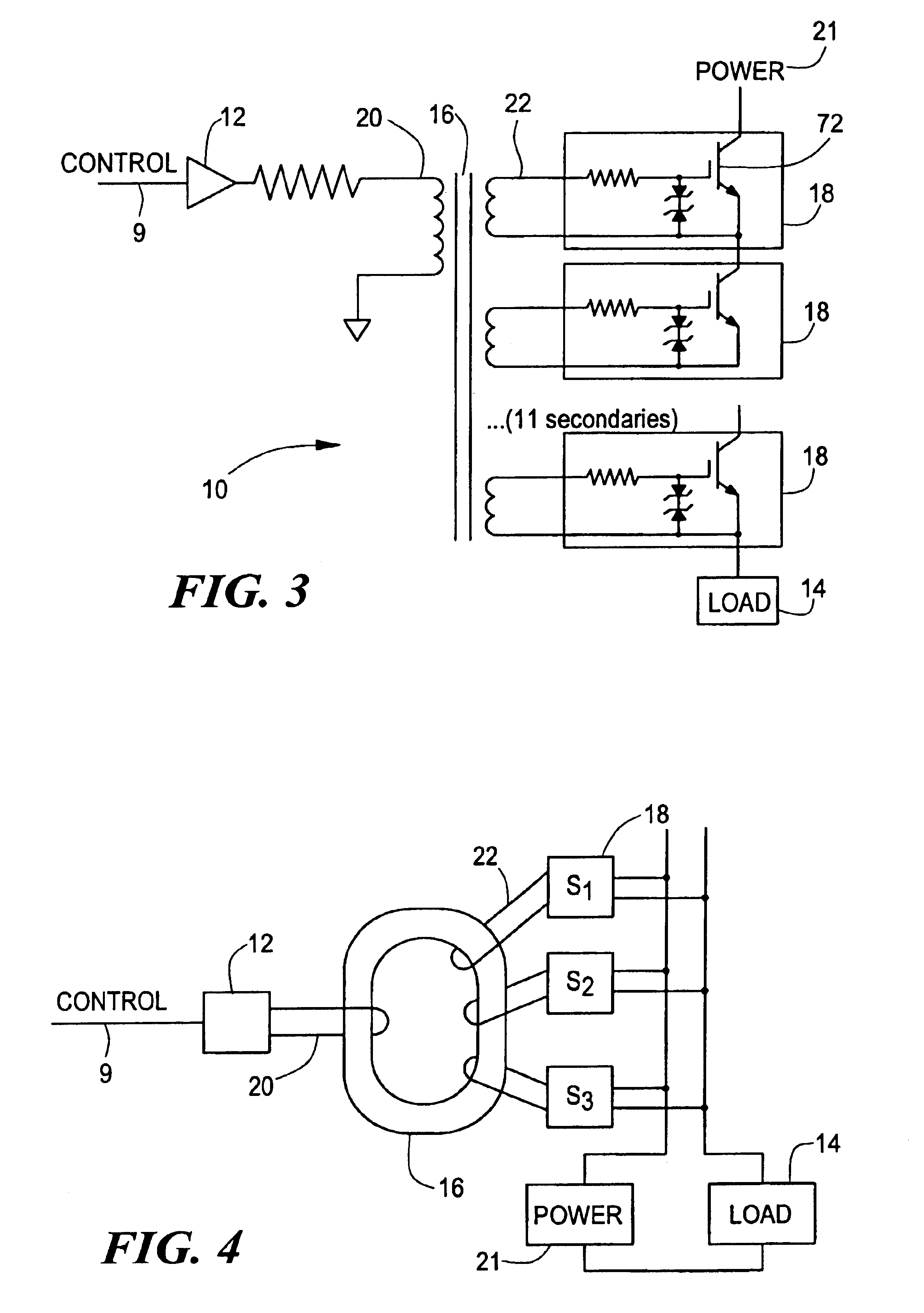
[0024]Modulators are electronic devices used to precisely regulate the delivery of high voltage, high current electrical pulses. A modulator can act as a simple series switch between a high power supply and its load (such as a klystron). Ideally, modulators have infinite voltage holdoff, infinite off-resistance, zero on-resistance, and fill immunity to transients and voltage reversals. Modulators are critical components of electronic systems used for numerous applications such as radar systems, particle accelerators, medical diagnostics and treatment equipment, and manufacturing equipment, such as ion implantation for semiconductor fabrication. In addition, new processes for food sterilization, waste treatment, and pollution control are also being developed which require the use of high power modulators.

[0025]Many high power modulators use pulse transformers to allow switching of the required pulse energy at low voltage. However, conventional pulse modulators generally require large...


PUM


Abstract

A compact transformer coupled modulator is described. The modulator includes a transformer comprising a primary and a plurality of secondary windings, where each secondary winding has an output terminal. The modulator also includes a plurality of switches, where each switch is associated with a respective secondary winding and has input and output terminals and a control terminal. The control terminal of each switch is in electrical communication with a respective output terminal of the plurality of secondary windings. Each of the plurality of switches is substantially simultaneously switched by an input signal applied to the primary.

Description

FIELD OF THE INVENTION[0001]This invention relates to the field of high voltage modulators and, more particularly, to solid state modulators for high voltage systems.BACKGROUND[0002]Reliable high-speed, high-power switching has a wide variety of applications such as radar and communications transmitters, ion implantation, particle accelerators, induction heating, and materials processing. Applications of high-speed, high-power switching require consistent, controllable, rapid, and cost-effective switching of high levels of electrical power. The components and technologies currently available to support these high-power switching applications were developed in the 1930's and 1940's. Despite the revolution in cost and performance that solid state technology has brought to nearly every other realm of electronics, progress with solid state high voltage and high power switching devices has been slow and improvements have been modest.[0003]For example, vacuum switch tubes or thyratrons, a...

Claims


Application Information

Patent Timeline
IPC IPC(8): H02M1/088H03K17/0812H03K17/10H03K17/691
CPCH02M1/088H03K17/0812H03K17/08122H03K17/08128H03K17/102H03K17/107H03K17/691
Inventor GAUDREAU, MARCEL P. J.KEMPKES, MICHAEL A.HAWKEY, TIMOTHY J.CASEY, JEFFREYMULVANEY, JAMES M.DANDRIGE, PETER A.
Owner DIVERSIFIED TECH INC
Why Eureka
Try Eureka