Optical deflector and method of producing same

a technology of optical deflector and optical lens, which is applied in the field of optical lens, can solve the problems of difficult to provide the action of the scanning mirror at a high speed, and significant increase in the moment of inertia of the scanning mirror, so as to achieve low distortion, high static flatness of the reflective surface, and large angle of deflection

Inactive Publication Date: 2005-05-31
CANON KK
View PDF16 Cites 61 Cited by
  • Summary
  • Abstract
  • Description
  • Claims
  • Application Information

AI Technical Summary

Benefits of technology

[0018]It is, therefore, an object of the present invention to provide an optical deflector that can be driven at a high speed with a low voltage, provides a large angle of deflection and a low distortion even in high speed

Problems solved by technology

However, these first and second conventional examples have problems described below.
Thus, there is a problem that it is difficult to provide both of action of the scanning mirror at a high speed and with a large angle of deflection and optical characteristics of the optical deflector.
Thus, there is another problem that the moment of inertia of the scanning mirror 1001 significantly increases, and the center of gravity of the scanning mirror 1001 is largely displaced from the torsion axis 1005 and a stable torsional vibration cannot be attained.
Thus, there is a problem that t

Method used


Image

  • Optical deflector and method of producing same
  • Optical deflector and method of producing same
  • Optical deflector and method of producing same

Examples


first embodiment

(First Embodiment)

(Entire Configuration and Mirror (Movable Plate))

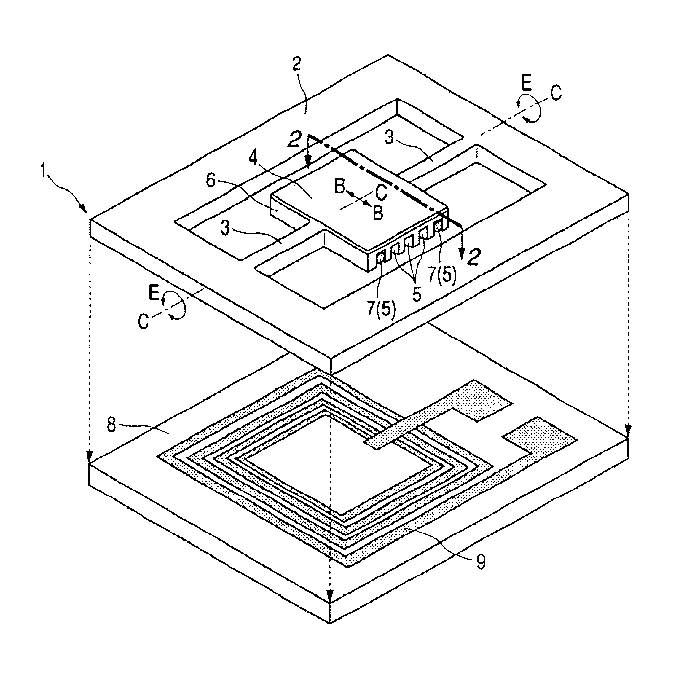
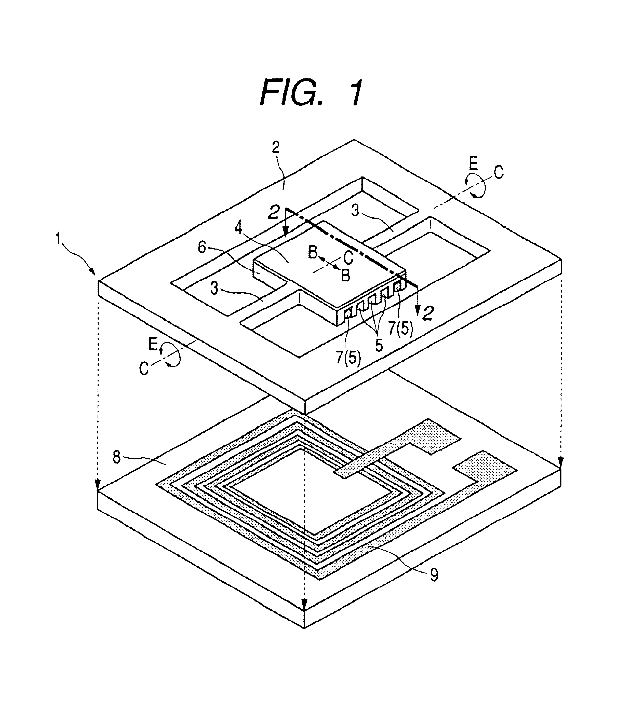
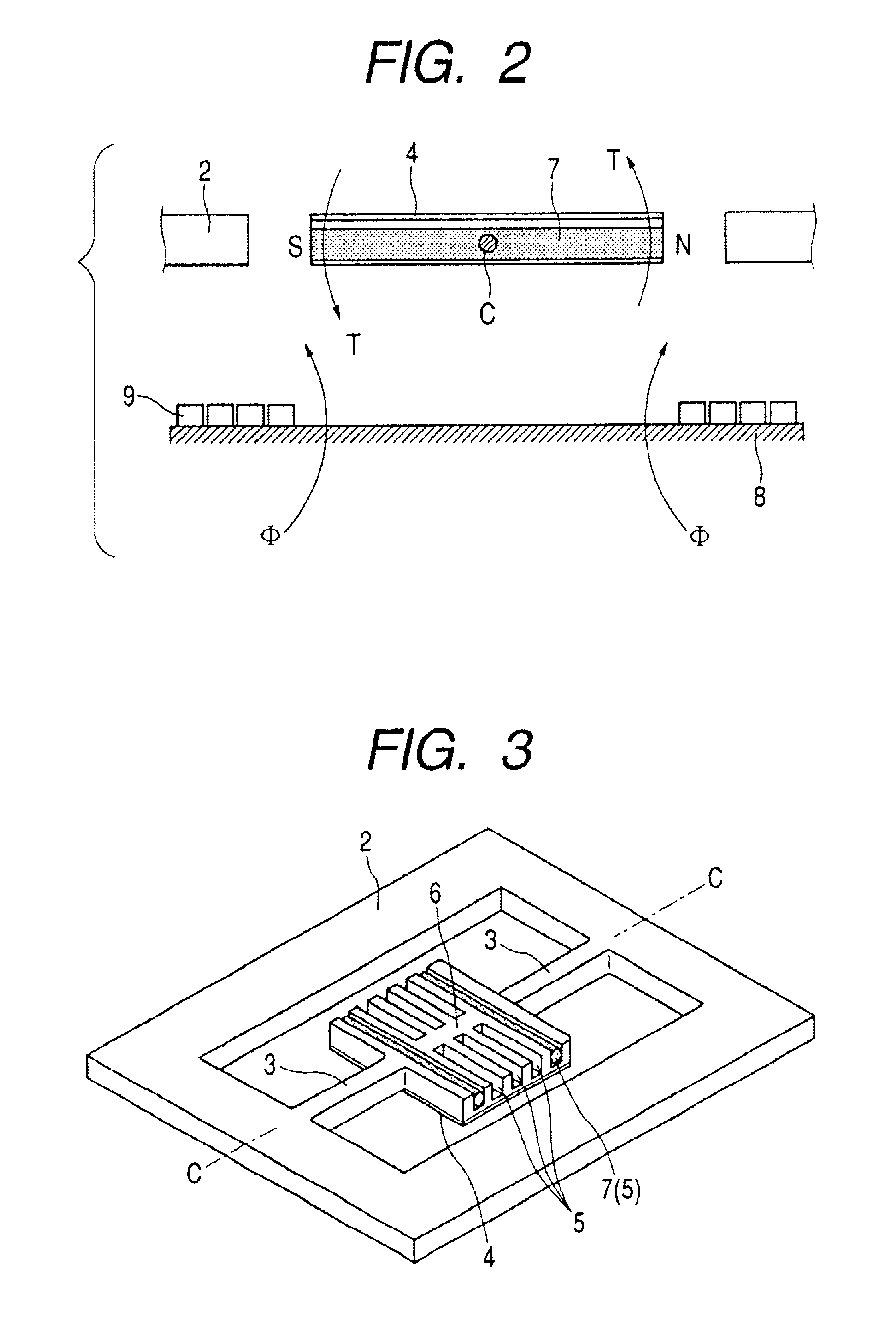
[0051]FIG. 1 is a perspective view showing a configuration of an optical deflector according to a first embodiment of the invention. In FIG. 1, an optical deflector 1 comprises a supporting substrate 2, a movable plate 6, and elastic supporting parts 3, the movable plate 6 being supported at both ends thereof on the supporting substrate 2 via the elastic supporting parts 3. The elastic supporting parts 3 support the movable plate 6 in such a manner that the movable plate 6 can be elastically and torsionally vibrated about a C axis (that is, a torsion axis) in a direction indicated by the arrow E. One surface of the movable plate 6 is a reflective surface 4 that constitutes a mirror surface, and torsional movement of the movable plate 6 in the E direction provides deflection of a light incident on the reflective surface 4 at a predetermined angle. The direction indicated by the arrow B in FIG. 1 is perpendicular to th...

second embodiment

(Second Embodiment)

[0068]FIG. 4 is a perspective view of an optical deflector according to a second embodiment of the invention. An optical deflector 21 of this embodiment is essentially the same in driving principle as the optical deflector 1 of the first embodiment. Furthermore, as in the first embodiment, the optical deflector 21 is integrally formed from single-crystal silicon by a micromachining technique, which is an application of the semiconductor producing technology.

[0069]The difference between FIG. 4 and FIG. 1 is the configuration of the supporting substrate 2, the elastic supporting parts 3, the movable plate 6, the recess 5, and the permanent magnet 7. These differences will be described in the following section. Here, in FIG. 4, parts identical to those in FIG. 1 are assigned the same reference numerals.

[0070]FIG. 5A is a cross-sectional view taken along the line 5A—5A in FIG. 4, FIG. 5B is a cross-sectional view taken along the line 5B—5B in FIG. 4, and FIG. 5C is a ...

third embodiment

(Third Embodiment)

[0082]FIG. 6 is a perspective view of an optical deflector according to a third embodiment of the invention.

[0083]An optical deflector 31 according to this embodiment has the supporting substrate 2 and the elastic supporting parts 3 similar to those of the optical deflector 21 of the second embodiment, which have the same effect as those of the optical deflector 21. Furthermore, as in the second embodiment, the optical deflector 31 is integrally formed from single-crystal silicon by a micromachining technique, which is an application of the semiconductor producing technology.

[0084]The difference of FIG. 6 from FIG. 4 is the configuration of the recess 5 and the permanent magnet 7, and these will be described in particular in the following. Here, in FIG. 6, parts identical to those in FIG. 4 are assigned the same reference numerals.

[0085]FIG. 7 is a cross-sectional view taken along the line 7—7 in FIG. 6. The inner surfaces of the recess 5 are constituted by (111)-e...


PUM

PropertyMeasurementUnit
Widthaaaaaaaaaa
Areaaaaaaaaaaa

Abstract

There are provided a small optical deflector that can be driven at a high speed with a low voltage, provides a large angle of deflection, has a low distortion even in high speed operation and has a high static flatness of a reflective surface, and a method of producing the optical deflector. The optical deflector drives a movable plate relative to a supporting substrate to deflect a light incident on a reflective surface and has a configuration in which at least two recesses are formed in a surface of the movable plate on which the reflective surface is not formed, and a magnetic material is provided in the recesses.

Description

BACKGROUND OF THE INVENTION[0001]1. Field of the Invention[0002]The present invention relates to an optical deflector that deflects incident light, a method of producing the same, and an optical device using the same.[0003]2. Related Background Art[0004]In recent years, with the development of microelectronics as represented by the increasing integration density of semiconductor devices, various devices have been enhanced in capability and reduced in size. For example, image display devices, such as laser beam printers and head-mounted displays, and optical intake units or the like of input devices, such as barcode readers, in which an optical deflector is used for optical scanning, have also been enhanced in capability and reduced in size and are being required to be further down-sized. Optical deflectors meeting such a requirement have been proposed in Japanese Patent Application Laid-Open No. 6-82711 (no corresponding document in foreign language) and Japanese Patent Application ...

Claims


Application Information

Patent Timeline
IPC IPC(8): G02B26/10G02B26/08H04N5/74B81B3/00B81C1/00B41J2/44H04N1/036H04N1/113
CPCG02B26/085G02B26/105H04N5/7441G02B26/10
Inventor KATO, TAKAHISAYAGI, TAKAYUKISHIMADA, YASUHIRO
Owner CANON KK
Why Eureka
Try Eureka