Digital adaptive sensorless commutational drive controller for a brushless DC motor

a dc motor and sensorless technology, applied in the direction of motor/generator/converter stopper, electronic commutator, dynamo-electric converter control, etc., can solve the problem of adding additional poles, increasing the complexity of the motor, and increasing the amount of hardware and wiring that is needed to drive the motor successfully

Inactive Publication Date: 2005-05-31
HALLIBURTON ENERGY SERVICES INC
View PDF28 Cites 57 Cited by
  • Summary
  • Abstract
  • Description
  • Claims
  • Application Information

AI Technical Summary

Benefits of technology

[0025]If the adaptive delay circuit does not sense a zero crossing in a predetermined period of time, the adaptive delay circuit generates a switching pulse to advance the commutation state machine. This function allows the adaptive delay circuit to act as a watchdog that is effective in starting the DC motor from stop or after a change of direction.

Problems solved by technology

However, the additional poles also increase motor complexity because stator winding current must be switched on and off to keep the stator poles ahead of the rotor poles as the rotor moves with respect to the stator.
While effective, these brushes were subject to mechanical wear over time.
Furthermore, this configuration added to the amount of hardware and wiring that was needed to successfully drive the motor.
These brushless DC motor solutions significantly reduced, if not eliminated, the conventional mechanical wear problem, but they still required extra hardware and wiring to provide the necessary position feedback.
One problem with using Back EMF signals to indicate rotor position is that the rotor must be moving to generate any Back EMF signal at all.
However, there are a number of drawbacks and limitations to these prior art motor controllers.
First, any controllers that use bipolar technologies are limited to use in reasonable operating temperatures.
These additional devices also lack long-term reliability at elevated operating temperatures.
Operating temperature range can also be prohibitive in processor designs, with 70° C. also being a typical maximum operating temperature for processors and DSPs.
Military grade DSPs offer a maximum operating temperature in the 120-130° C. range, but this may still limit applicability to high temperature (in excess of 150° C.) environments, such as those found in proximity to combustion engines or downhole drilling applications.
A second problem with prior art brushless, sensorless DC motor controllers is complexity and reliability.
These analog components tend to inhibit the long-term reliability of these designs.
Other designs employing processors are even more complex and expensive.
This complexity often hampers time to market.
Further, it is generally accepted that designs that are more complex exhibit lower long-term reliability.
Existing controllers are often difficult to tune and may require the changing of analog components or program code.

Method used


Image

  • Digital adaptive sensorless commutational drive controller for a brushless DC motor
  • Digital adaptive sensorless commutational drive controller for a brushless DC motor
  • Digital adaptive sensorless commutational drive controller for a brushless DC motor

Examples


Embodiment Construction

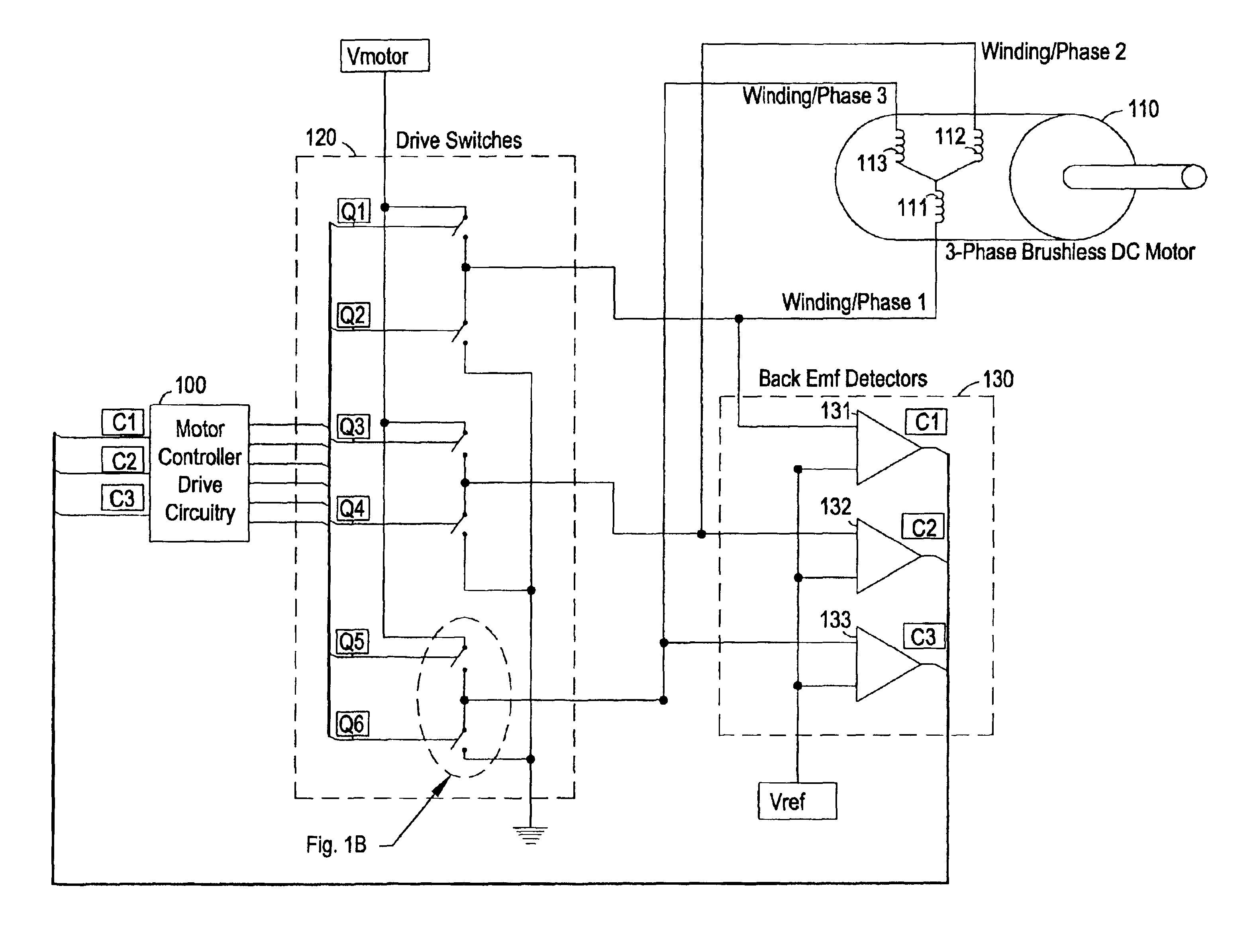
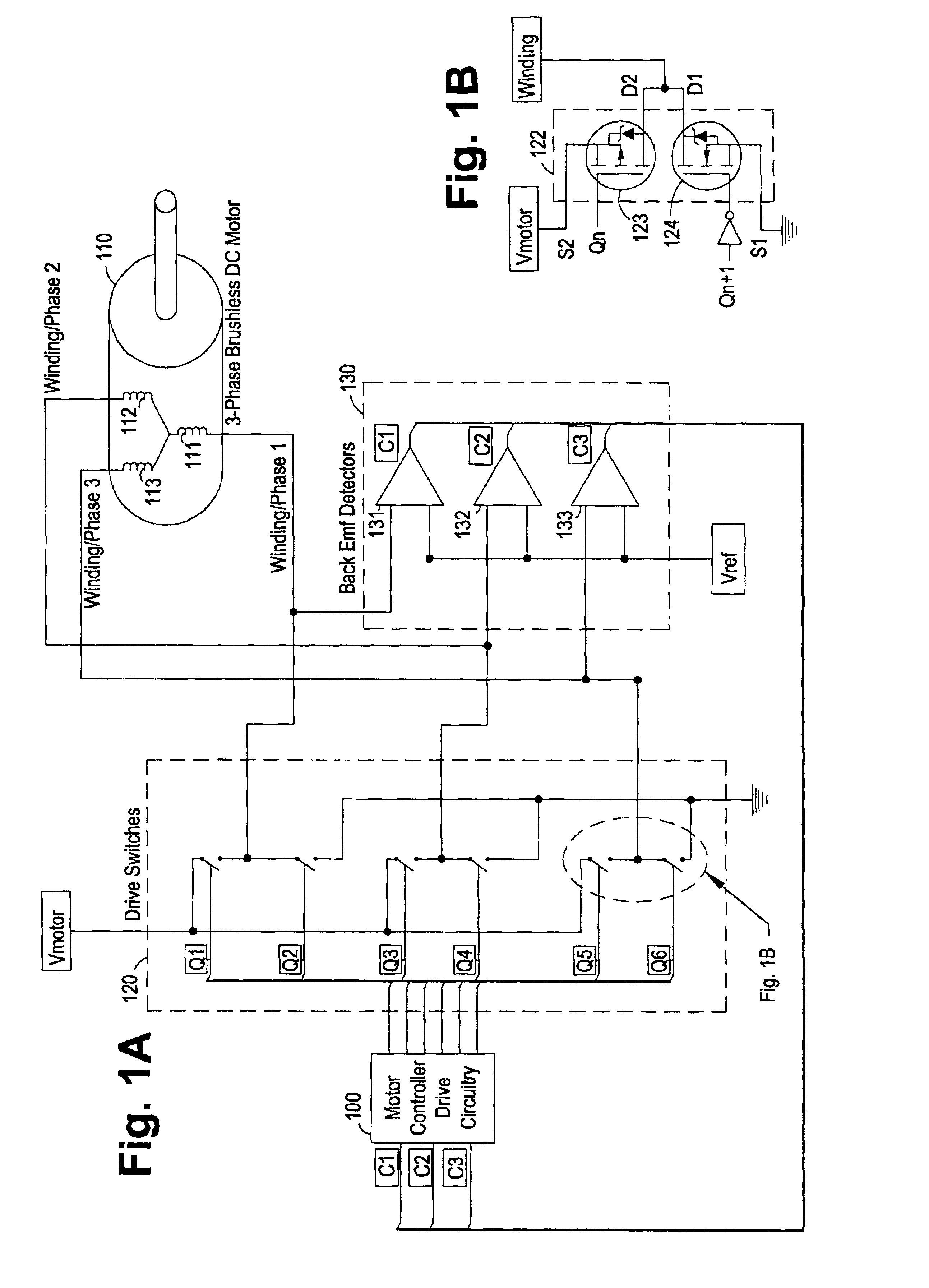
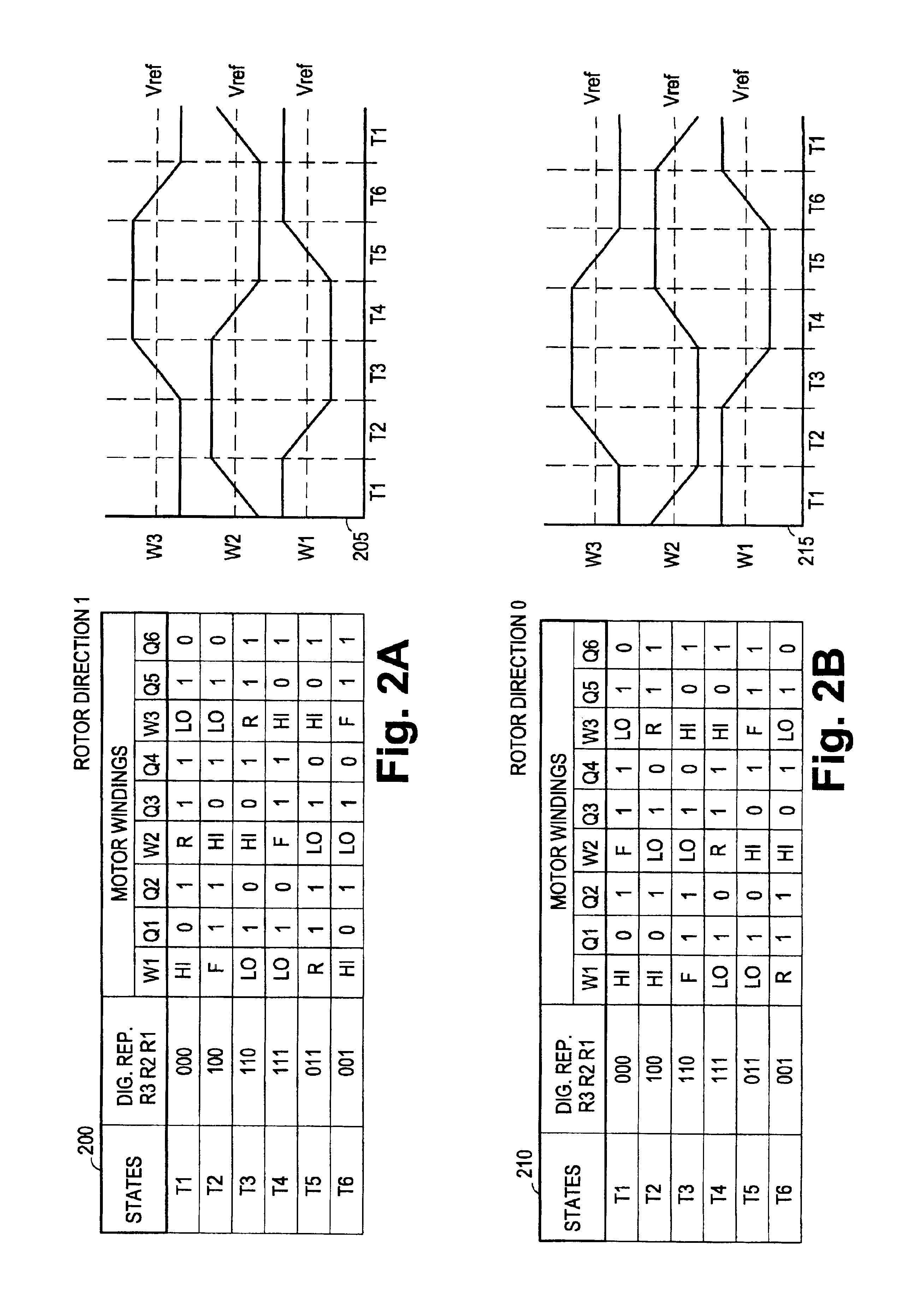
[0044]The preferred embodiment described herein generally discloses a digital motor controller drive circuit configured to provide commutation signals to a brushless, sensorless DC motor. The motor controller preferably resides in a feedback loop that comprises drive switches, commonly implemented using MOSFET switches, a three-phase brushless DC motor, and Back Electromotive Force (BEMF) detectors. The motor controller drive circuitry preferably receives digital signals from the BEMF detectors that indicate whether the voltage on the various windings are above a threshold and compares these levels with a previously detected level to determine whether the winding voltages are as expected. By expected, it is intended that the two levels—a presently detected level and the immediately prior detected level—are the same. If the voltage levels are as expected, the signature analyzer waits for a zero crossing before transmitting a commutation pulse. However, when the levels are different, ...


PUM


Abstract

A digitally adaptive controller circuit for commutating a brushless, sensorless, DC motor in either of two directions adapted to receive digital back electromotive force (BEMF) detector signals. The digital circuit is driven by an input clock that is adjustable to configure the motor controller for use with a broad range of DC motors. The circuit includes commutational logic that decodes a current commutational state and a user-definable binary direction input into logic levels for digital control signals for controlling motor drive switches. The circuit also includes a signature analyzer to compare logic levels in the BEMF detector signals with expected logic levels based on an expected rotor position and direction of rotation. The digital circuit commutates the motor if the logic levels in the BEMF detector signals are at the expected logic levels. The digital circuit is compact and simple enough to be deployed onto a single programmable logic device.

Description

CROSS-REFERENCE TO RELATED APPLICATIONS[0001]Not applicable.STATEMENT REGARDING FEDERALLY SPONSORED RESEARCH OR DEVELOPMENT[0002]Not applicable.BACKGROUND OF THE INVENTION[0003]1. Field of the Invention[0004]The present invention generally relates to brushless, sensorless, DC motor controllers. Specifically, the present invention relates to a completely digital logic implementation of a brushless, sensorless DC motor controller that uses back electromotive force values from the DC motor to selectively switch power to windings in the DC motor stator.[0005]2. Background of the Invention[0006]In conventional brushless DC motors, a displacing force (rotational or linear) is generated in the movable rotor portion of the motor by inducing a current in the stator windings. This stator winding current creates a stator magnetic field that causes the armature field in the motor rotor to attempt to align with the induced stator field. If a constant DC voltage is applied to a single coil or win...

Claims


Application Information

Patent Timeline
Patent Type & Authority Patents(United States)
IPC IPC(8): H02P6/18H02P6/14
CPCH02P6/003H02P6/12H02P6/20H02P6/16H02P6/182H02P6/142H02P6/15H02P6/30
Inventor MASINO, JAMES E.
Owner HALLIBURTON ENERGY SERVICES INC
Why Eureka
Try Eureka