
Exhaust emission control system for internal combustion engine

a technology of exhaust emission control and internal combustion engine, which is applied in electrical control, lighting and heating apparatus, separation processes, etc., can solve the problems of deviating from the optimum timing of regeneration process timing and inaccurate estimation of sulfur oxide absorbed in the nox removal devi

Inactive Publication Date: 2005-06-07
HONDA MOTOR CO LTD
View PDF14 Cites 51 Cited by
  • Summary
  • Abstract
  • Description
  • Claims
  • Application Information

AI Technical Summary

Benefits of technology

[0006]Accordingly, the present invention provides an exhaust emission control system that can accurately estimate the amount of sulfur oxide absorbed in the NOx removing device to thereby execute the regeneration process for the sulfur-poisoned NOx removing device at the optimum timing.
[0008]With this configuration, the amount of change (i.e., absorption amount or discharge amount) per unit time in the amount of sulfur oxide absorbed in the nitrogen oxide removing device is estimated according to the air-fuel ratio of an air-fuel mixture supplied to the engine and the operating condition of the engine, and the amount of change estimated above is accumulated to thereby estimate the amount of sulfur oxide absorbed in the nitrogen oxide removing device. Accordingly, the estimation of the amount of sulfur oxide can be made more accurately as compared with the prior art, and the regeneration process for the sulfur-poisoned nitrogen oxide removing device can be executed at an optimum timing.
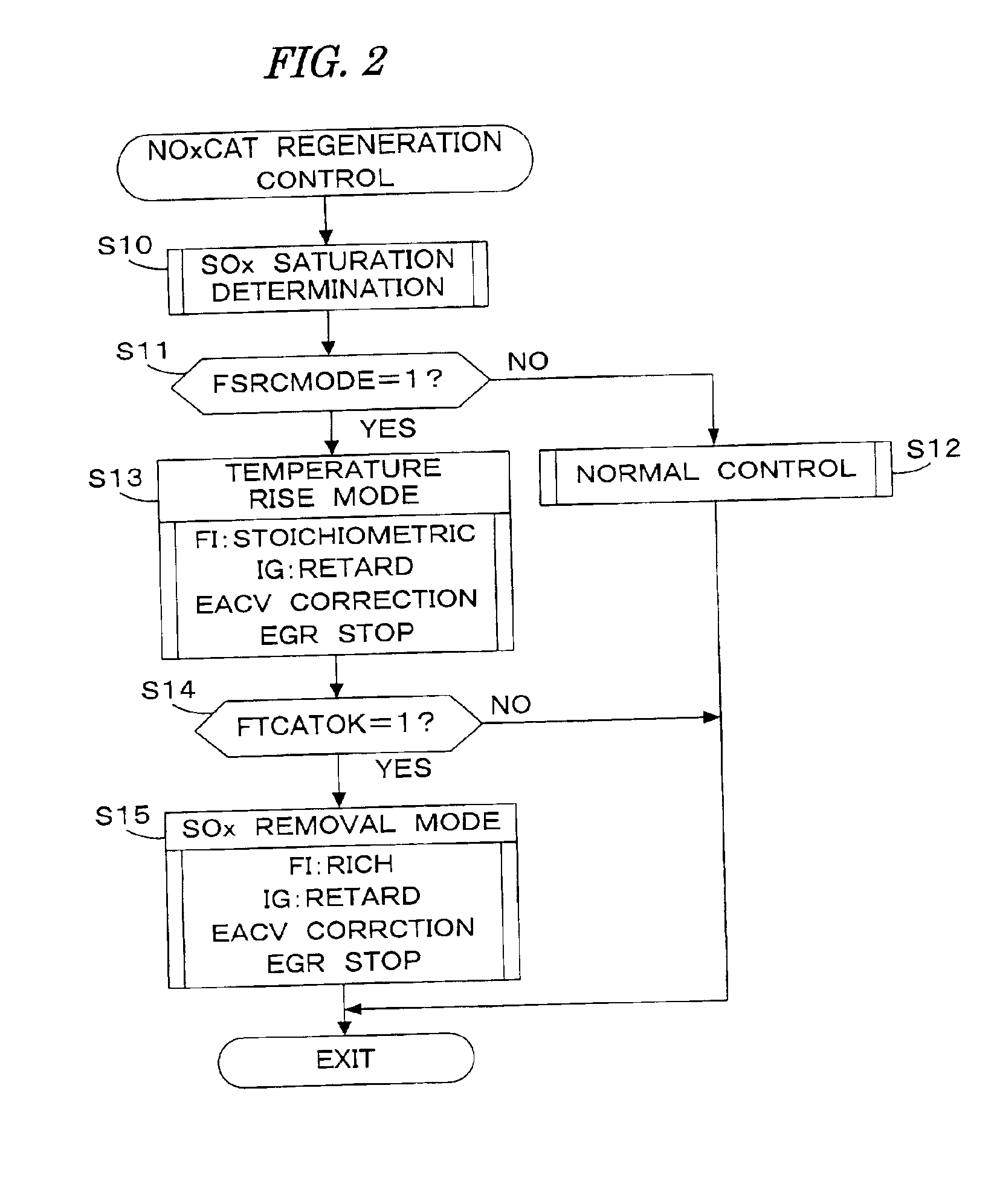
[0010]The amount of sulfur oxide absorbed in the nitrogen oxide removing device increases when the air-fuel ratio is set in a lean region with respect to the stoichiometric ratio. When the air-fuel ratio is set in the vicinity of the stoichiometric ratio or in a rich region with respect to the stoichiometric ratio, the amount of sulfur oxide absorbed in the nitrogen oxide removing device increases or decreases according to the engine operating condition. Accordingly, the first, second, and third estimating means are used to estimate the amount of change in the sulfur oxide amount when the air-fuel ratio is set in the vicinity of the stoichiometric ratio, the amount of change when the air-fuel ratio is set in the lean region, and the amount of change when the air-fuel ratio is set in the rich region according to the engine operating condition, thereby accurately estimating the amount of change in the sulfur oxide amount (i.e., the absorption amount or the discharge amount) per unit time.
[0014]Preferably, the sulfur oxide removing module retards the ignition timing of the engine from a normal set value, stops the exhaust gas recirculation, and controls the amount of intake air supplied to the engine so that the output torque of the engine does not change when removing the sulfur oxide.

Problems solved by technology

However, if the technique described in the above publication is applied, the following problem arises.
However, such discharge of the sulfur oxide during the stoichiometric operation or the rich operation is not considered in the conventional system described in the above publication, so that the estimation of the amount of sulfur oxide absorbed in the NOx removing device becomes inaccurate.
This causes a problem in that the timing of execution of the regeneration process may deviate from the optimum timing.

Method used


Image

  • Exhaust emission control system for internal combustion engine
  • Exhaust emission control system for internal combustion engine
  • Exhaust emission control system for internal combustion engine

Examples


Embodiment Construction

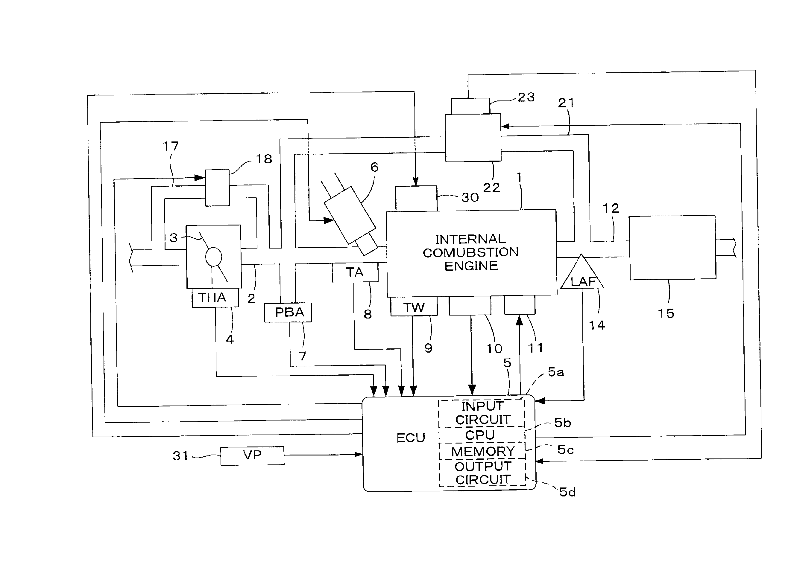
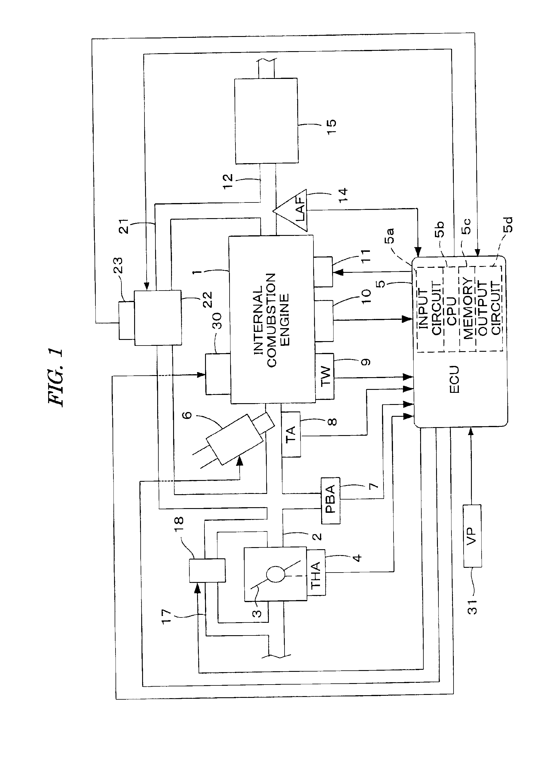
[0023]A preferred embodiment of the present invention will now be described with reference to the drawings.

[0024]Referring to FIG. 1, there is schematically shown a general configuration of an internal combustion engine (which will be hereinafter referred to as “engine”) and a control system therefor, including an exhaust emission control system according to a preferred embodiment of the present invention. The engine is a four-cylinder engine 1, for example, and has an intake pipe 2 provided with a throttle valve 3. A throttle valve opening (THA) sensor 4 is connected to the throttle valve 3, so as to output an electrical signal corresponding to an opening angle of the throttle valve 3 and to supply the electrical signal to an electronic control unit (which will be hereinafter referred to as “ECU”) 5 for controlling the engine 1.

[0025]An auxiliary air passage 17 bypasses the throttle valve 3 and is connected to the intake pipe 2. The auxiliary air passage 17 is provided with an auxi...


PUM

PropertyMeasurementUnit
temperatureaaaaaaaaaa
crank angle periodaaaaaaaaaa

Abstract

An exhaust emission control system for an internal combustion engine, having a nitrogen oxide removing device provided in an exhaust system of said engine for absorbing nitrogen oxide contained in exhaust gases in an exhaust lean condition. An amount of change per unit time in the sulfur oxide amount absorbed in the nitrogen oxide removing device is estimated according to the air-fuel ratio of an air-fuel mixture supplied to said engine and the operating condition of said engine. The estimated amount of change is accumulated to thereby estimate the sulfur oxide amount absorbed in the nitrogen oxide removing device. The sulfur oxide is removed from the nitrogen oxide removing device when the estimated sulfur oxide amount has reached a set value.

Description

BACKGROUND OF THE INVENTION[0001]The present invention relates to an exhaust emission control system for an internal combustion engine having a nitrogen oxide (NOx) removing device in an exhaust system, and more particularly to an exhaust emission control system capable of performing a regeneration process for the NOx removing device in the case that it is deteriorated by sulfur poisoning.[0002]A conventional exhaust emission control system known in the art includes a NOx removing device in an exhaust system of an internal combustion engine. In this exhaust emission control system, NOx is absorbed by the NOx removing device in a lean operation where the air-fuel ratio is set in a lean region with respect to a stoichiometric ratio, and NOx absorbed by the NOx removing device is reduced to be discharged by suitably executing enrichment of the air-fuel ratio. The NOx absorption capacity of the NOx removing device decreases from sulphur poisoning because it also absorbs oxides of sulfur...

Claims


Application Information

Patent Timeline
Patent Type & Authority Patents(United States)
IPC IPC(8): B01D53/94F02D41/02F01N3/08
CPCB01D53/9409B01D53/949B01D53/9495F01N3/0842F02D41/028B01D2251/204F02D2200/0818B01D2255/91F01N2570/04B01D2251/208
Inventor HASHIMOTO, AKIRA
Owner HONDA MOTOR CO LTD
Learn More