Oil drain plug of engine

a technology of oil drain plug and engine, which is applied in the direction of machines/engines, couplings, lubrication check valves, etc., can solve the problems of oil contaminated, degraded oil, loss of lubricating performance, etc., and achieves the effect of facilitating the manufacturing of oil drain plugs, reducing costs, and improving productivity

Inactive Publication Date: 2005-06-07
TAKAHARA TAMOTSU +1
View PDF16 Cites 19 Cited by
  • Summary
  • Abstract
  • Description
  • Claims
  • Application Information

AI Technical Summary

Benefits of technology

[0028]The invention provides an advantage that the valve seat, which is critical to ensure prevention of oil leakage when the built-in normally closed valve is closed, can be formed from a member that is designed independently of and separately from the bolt-type member in material, shape, etc.
[0029]In the invention according to the first aspect, in each of the aforementioned aspects, the cylindrical bolt-type member is adapted to allow a spring member accommodating portion for normally biasing the movable valve body member to the closed position, a portion for accommodating the movable valve body member, and a portion for fixing the valve seat forming member to gradually increase in diameter, from one end portion toward the other end portion inside the oil pan. This gradual increase in diameter is necessary in the inner wall of the valve body member, for the reason that the wall thickness will become too thin at point X, thereby causing when the invention is installed into the oil pan and torque is applied the possibility of cracking. On the other hand, if the inner wall of the valve body member does not employ a gradual opening and the length of the bold-shape component protruding from the oil pan becomes long to compensate for the thin wall the possibility of rubbing the ground when the car is in motion. According to this invention, the spring for biasing the built-in valve to the normally closed position, the movable valve body member, and the valve seat forming member are disposed in the oil drain passage of the cylindrical bolt-type member in that order. The plug according to the present invention can be characterized by the press fitting of the end portion on the other end of the cylindrical bolt-type member so as to fix the valve seat forming member. This facilitates the manufacturing of the oil drain plug, thus improving productivity and providing the plug at lower costs than were possible with prior inventions.

Problems solved by technology

The oil will be degraded over time with use to lose the lubricating performance desired.
In addition, the oil will be contaminated by particles caused by wearing or sludge.
As described above, contaminants in the oil are filtered by the filter 104 in general in the course of circulation thereof, however, there is a limit to removing foreign matter by means of the filter.
In addition, the degradation of the oil itself with time cannot be avoided.
However, the aforementioned oil replacement is rather cumbersome in that the plug is first removed from the oil drain hole 105 and the plug is threaded into the hole again after the oil has been drained.
In addition, it cannot be avoided for the operator to be smeared with the oil.
However, the upper drainage methods can provide no means for checking whether the distal end of the tube has reached the bottom portion of the oil pan since the tube is inserted from above the crankshaft or other complicated mechanisms that are accommodated in a narrow limited space.
For this reason or another, it is difficult to completely drain the degraded oil.
Thus, it may not be found that the degraded oil has not been replaced properly until the refilled oil is checked.
In addition, the upper drainage methods have not been employed widely because the methods cannot provide means for readily eliminating metal particles and the like accumulated on the bottom portion of the oil pan.
However, when the inventor actually tried draining oil using the plug having the normally closed valve built therein according to the aforementioned prior-art method, it was found that the plug could be incorporated into only limited types of automobiles due to some problems that some automobiles were not adapted to have the plug attached thereto.
Accordingly, a further detailed study was made and it was found that these problems were originated from slight displacements in various mechanisms in the oil pan, which was designed in accordance with specifications different depending on the type of automobiles and which did not always require to be assembled with high accuracy.
In this case, presence of a structure on the axial line of the oil drain hole in the oil pan would cause the plug to be insufficiently threaded into the hole, thus resulting in defective attachment.
In some cases, the plug cannot be attached to the automobile at all due to the design specification thereof.
In addition, although the design specification allows the attachment of the plug, a displacement of a few millimeters occurring during the manufacture of the oil pan may make it impossible to attach the plug thereto.
Thus, the presence of the structure mentioned above would lead to a drawback that the plug can be attached to the oil drain hole but the valve cannot be opened.
This presents more detrimental effects in practice.

Method used


Image

  • Oil drain plug of engine
  • Oil drain plug of engine
  • Oil drain plug of engine

Examples


Embodiment Construction

[0035]An embodiment of the present invention will be explained below in more detail with reference to the drawings.

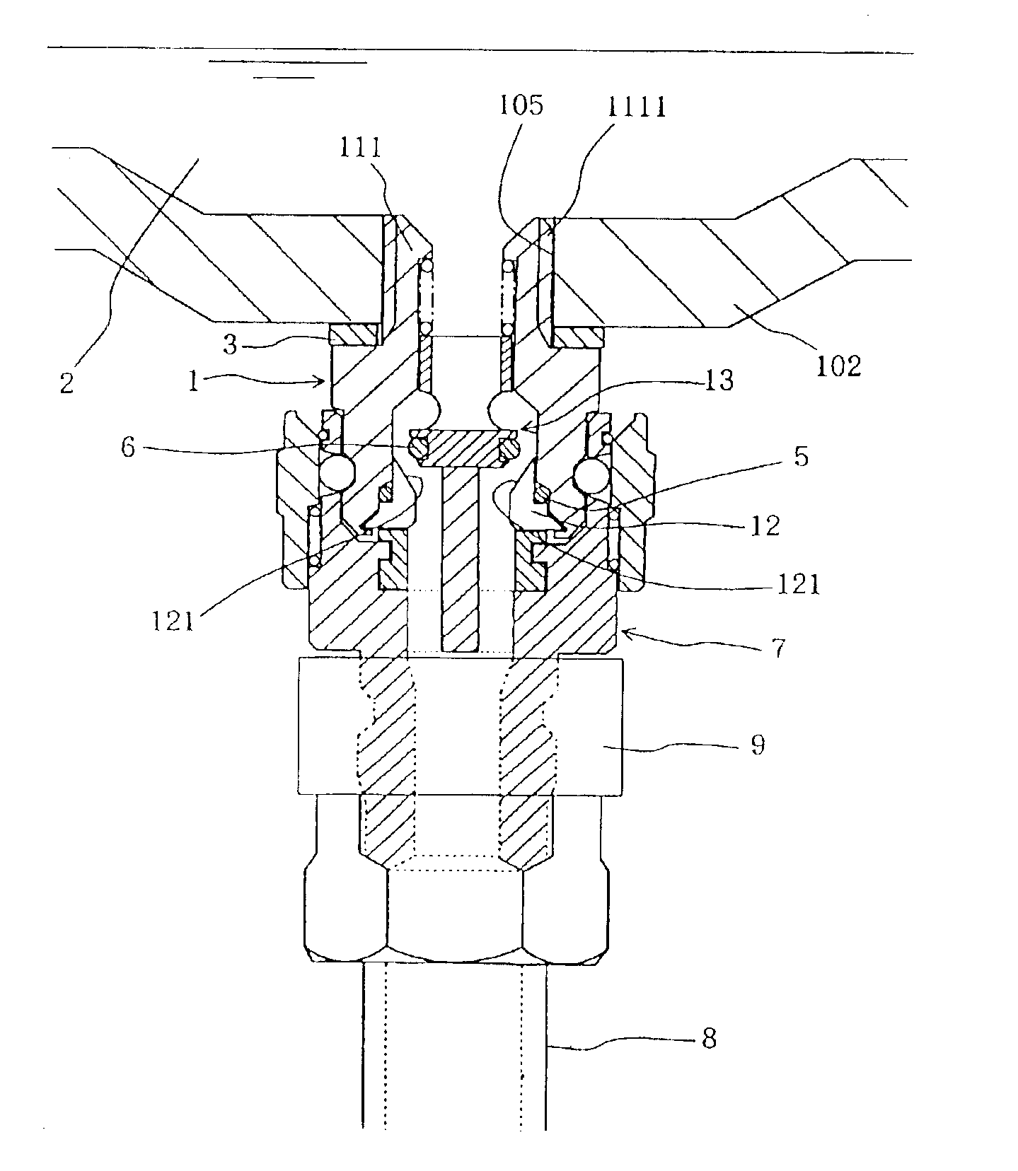
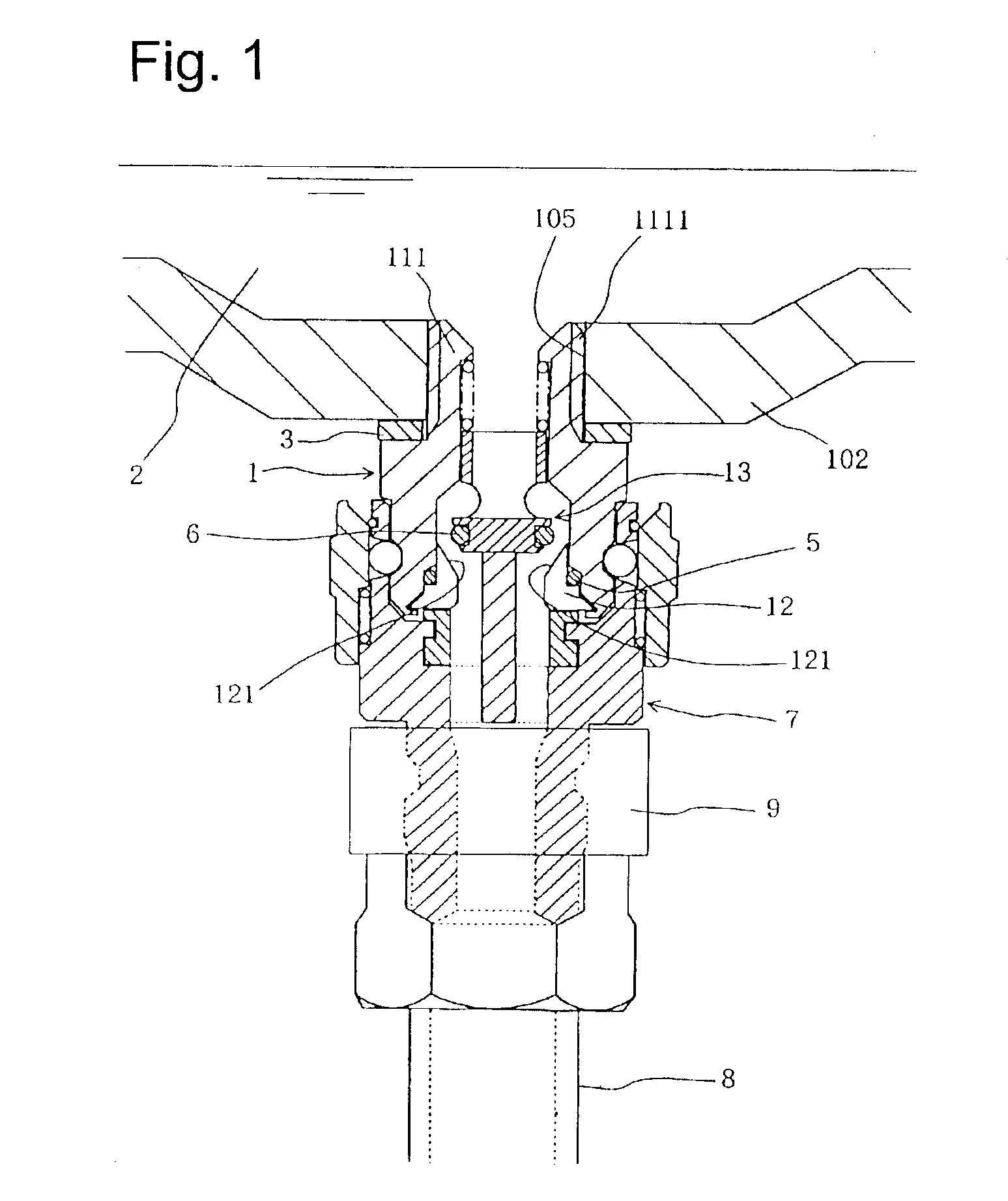
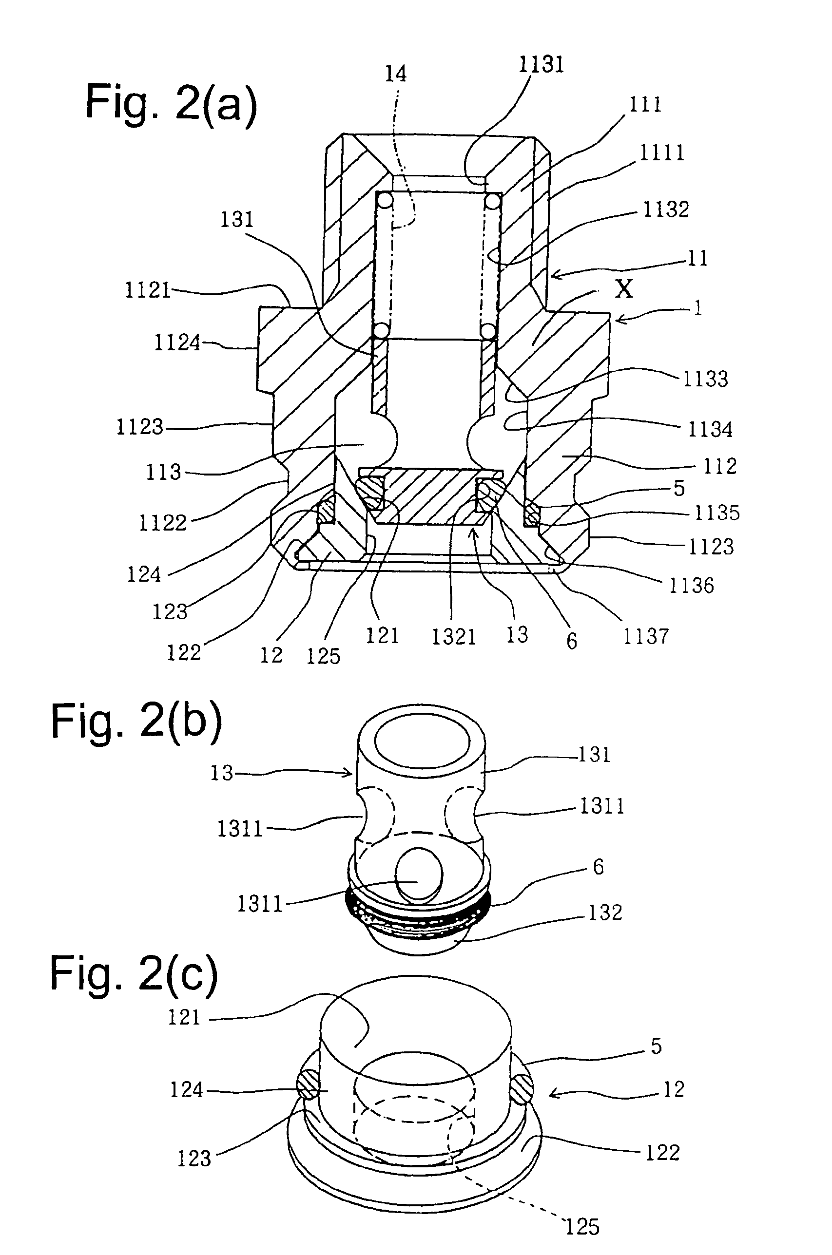
[0036]The embodiment is illustrated in FIGS. 1 to 4. FIG. 1 illustrates an oil drain plug according to the present embodiment attached to an oil pan, in which an oil drain dedicated jig is attached thereto for draining oil. FIGS. 2(a)-2(c) show explanatory views illustrating the oil drain plug according to the embodiment. FIG. 3 illustrates the dedicated jig for opening the normally closed valve of the oil drain plug according to the embodiment. FIG. 4 illustrates a cap employed for protecting the oil drain plug under usual service conditions other than the oil replacement.

[0037]Referring to FIG. 1, an oil pan is represented at 102 and an oil drain hole (female screw hole) is represented at 105 which is provided in the bottom portion of the oil pan 102. These are adapted in the same way as those of FIG. 5. The oil drain hole 105 is usually closed tightly by means of a s...


PUM


Abstract

A new type of plug incorporating a normally closed valve for draining oil from an oil pan of a car engine, wherein the normally closed valve is incorporated in a through hole provided as an oil draining path in a bolt type member fixed to the oil pan, an oil draining dedicated jig is assembled to the plug so as to open the normally closed valve in order to drain the oil contained in the oil pan by sucking it with a negative pressure, a movable valve disc member installed in the through hole is installed so that it is engaged with a valve seat provided near the outer end part of the through hole by a coiled spring so as to form the normally closed valve, and the tip end of the plug is made flush generally with the internal surface of the oil pan so as to prevent any structure from projecting toward the inside.

Description

CROSS REFERENCE TO RELATED APPLICATION[0001]This is a continuation-in-part application of patent application Ser. No. 09 / 647,806 filed on Oct. 19, 2000 now abandoned.BACKGROUND OF THE INVENTION AND RELATED ART STATEMENT[0002]The present invention relates to an oil drain plug for use with the oil pan of automobile engines.[0003]Conventionally, automobile engines are provided with a mechanism for circulating lubricating oil (oil) through predetermined portions in order to allow the moving parts to move smoothly. The oil will be degraded over time with use to lose the lubricating performance desired. In addition, the oil will be contaminated by particles caused by wearing or sludge. Accordingly, the degraded oil is replaced at regular intervals (in general, at regular distances of travel about 3,000 to 5,000 km) from the viewpoint of preventing damage to the engine body and the like.[0004]FIG. 5 is an explanatory view illustrating an example of an ordinary conventional engine having a ...

Claims


Application Information

Patent Timeline
Patent Type & Authority Patents(United States)
IPC IPC(8): F01M11/04
CPCF01M11/045F01M11/0408
Inventor TAKAHARA, TAMOTSU
Owner TAKAHARA TAMOTSU
Why Eureka
Try Eureka