
Packaging device for a catheter assembly

a technology for packaging devices and catheters, applied in the directions of catheters, bandages, transportation and packaging, etc., can solve the problems of thrombotic stroke, cardiac arrest, and major cause of death, and achieve the effects of reducing the risk of cardiac arres

Inactive Publication Date: 2005-06-07
MEDTRONIC VASCULAR INC
View PDF14 Cites 24 Cited by
  • Summary
  • Abstract
  • Description
  • Claims
  • Application Information

AI Technical Summary

Benefits of technology

[0008]One aspect of the present invention is a catheter packaging device having a base portion and a catheter-holding portion. The base portion includes a bottom surface, a perimeter wall, and at least one retaining member extending inward from the perimeter wall. The catheter-holding portion includes a protective Well and at least on

Problems solved by technology

Heart disease, specifically coronary artery disease, is a major cause of death, disability, and healthcare expense in the United States and other industrialized countries.
The clot may further reduce or entirely prevent the flow of oxygen-rich blood to heart muscles, causing a heart attack.
Alternatively, the clot may break off and lodge in the vessel of another organ, such as the brain, resulting in a thrombotic stroke.
Soon after the procedure, however, a significant proportion of treated vessels restenose.
However, if the coating remains in direct contact with another material for an extended period of time, for example, during shipping and storage, the therapeutic agent may migrate into the other material, resulting in delivery of a lower dose of the therapeutic agent than intended.
Alternatively, components of the other material may migrate into the therapeutic coating, again leading to impaired performance of the therapeutic agent.
Uncoated stents that have undergone chemical or other treatments may also be at risk of damage from contact with packaging material.
The treated stent may be damaged not only by extended contact, but also by brief contact that results in scratching, as might occur when a protective sleeve is dragged across the surface of a stent.

Method used


Image

  • Packaging device for a catheter assembly
  • Packaging device for a catheter assembly
  • Packaging device for a catheter assembly

Examples


Embodiment Construction

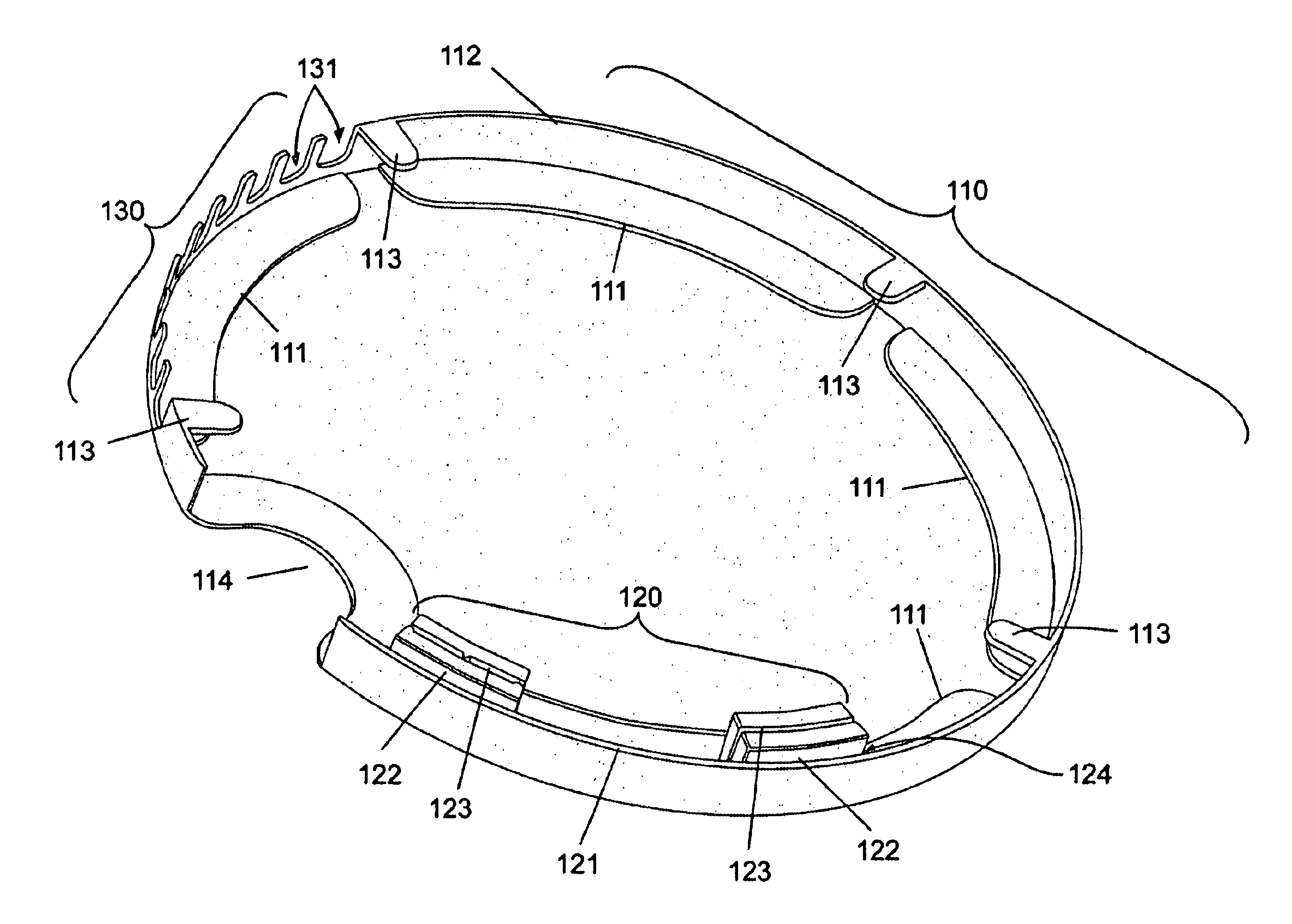
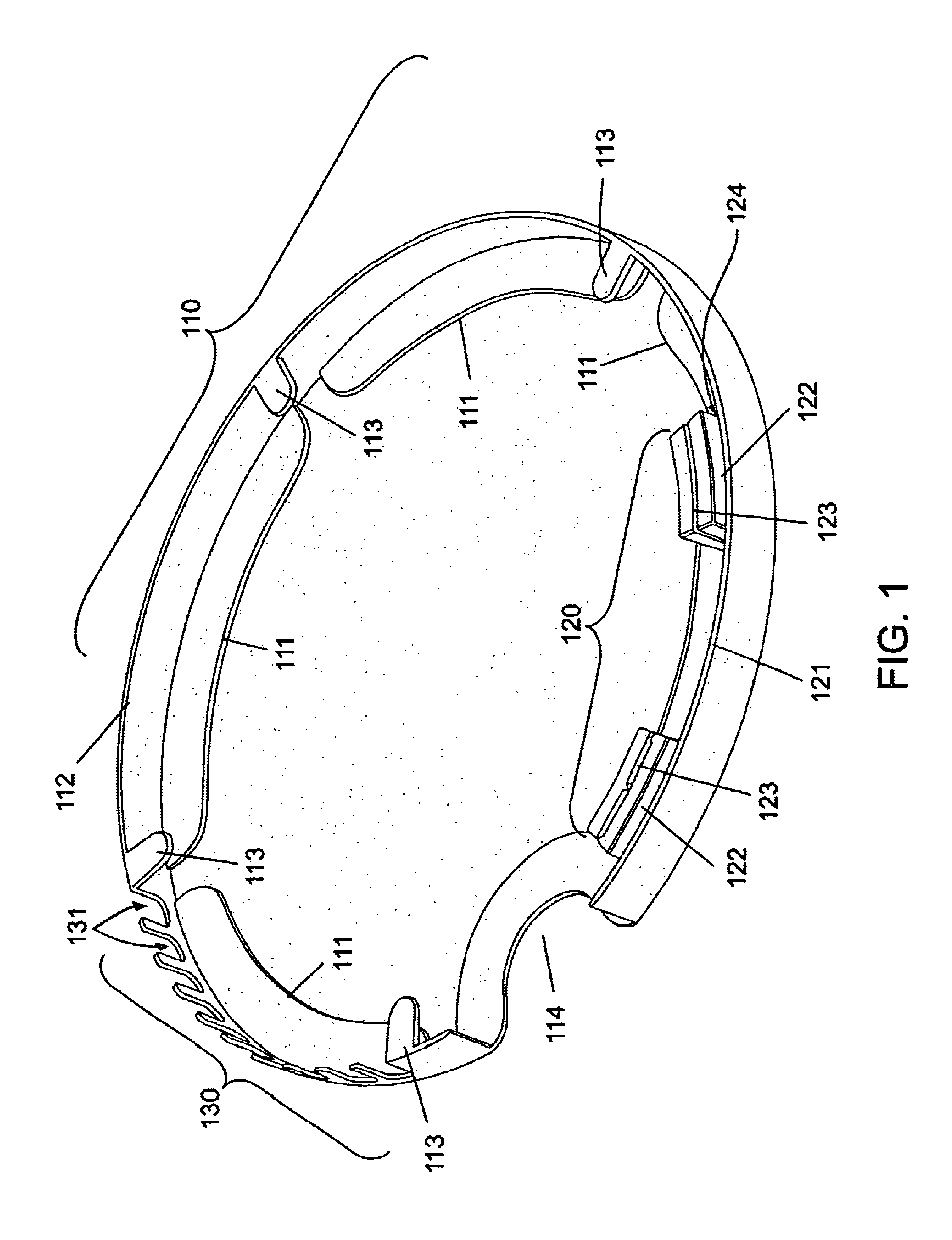
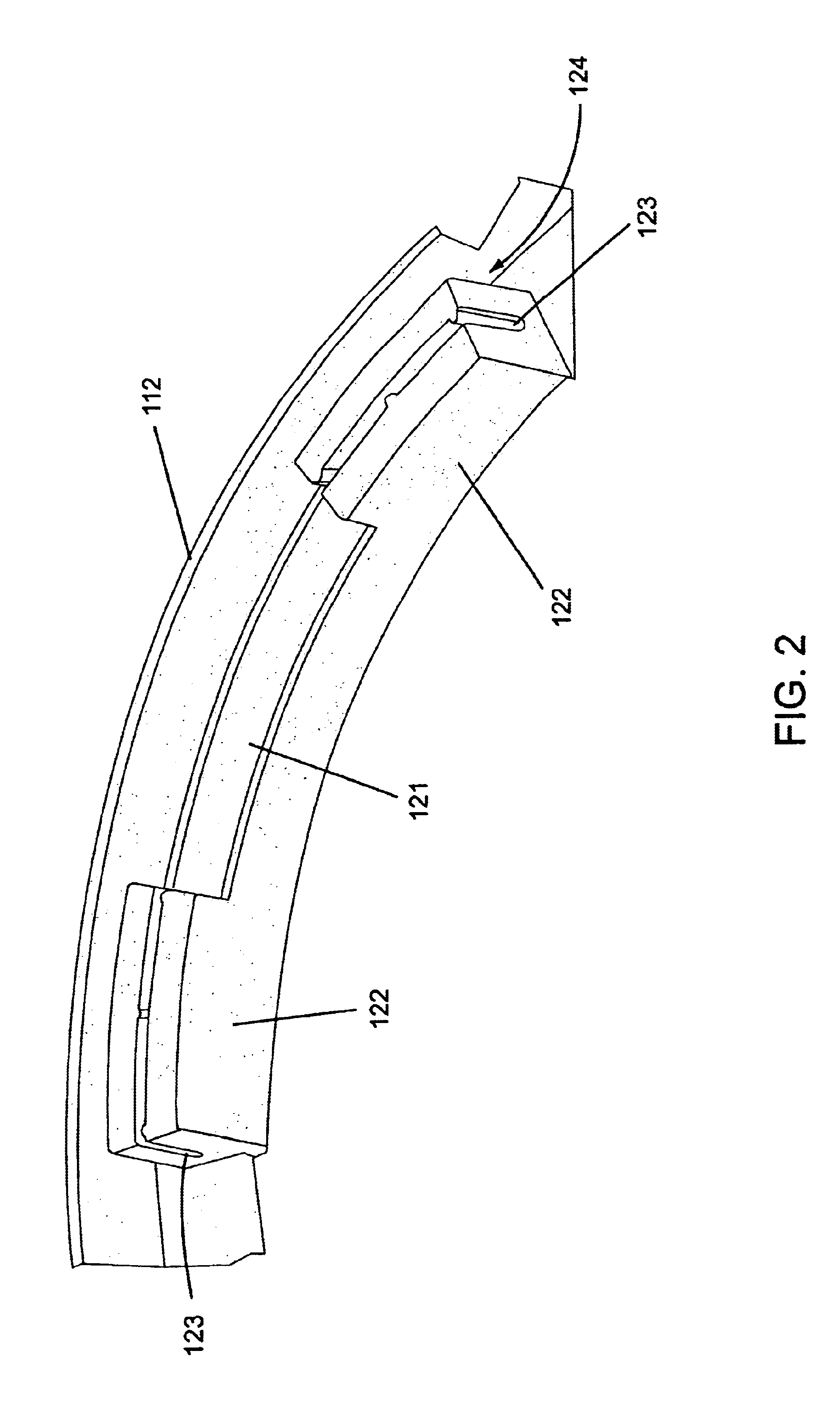
[0016]One aspect of the present invention is a catheter packaging device. One embodiment of the device, in accordance with the present invention, is illustrated in FIG. 1 at 100 and in enlarged, fragmentary views in FIG. 2 and FIG. 3.

[0017]Device 100 may include a base portion 110, a catheter-holding portion 120, and a luer-holding portion 130. Base portion 110 may include a bottom surface 111, a perimeter wall 112, at least one retaining member 113, and a recess 114 for finger access to a stored catheter. Catheter holding portion 120 may include a protective well 121 and at least one support member 122. Support member 122 may include an elongate channel 123. A channel 124 may be provided between the catheter-holding portion 120 and the perimeter wall to contain a portion of a coiled catheter. Luer-holding portion 130 may include at least one opening 131 into which a wing section or side arm of a luer may be placed.

[0018]Device 100 and its base portion 110 may be ringlike, as shown ...


PUM


Abstract

The present invention protects a catheter during shipment and storage. The device holds a portion of the catheter suspended such that the portion does not contact the device. When the suspended portion includes a stent treated with a therapeutic coating, the coating is protected from physical damage and from the risk that extended contact of the coating with packaging materials may result in the therapeutic agent migrating out of the coating and into the packaging materials or components of the packaging materials migrating into the therapeutic coating, both of which can occur if a therapeutic coating remains in contact with another material for an extended period of time. A catheter bearing an untreated stent, a balloon catheter, and other types of catheter would be similarly protected from physical or chemical damage.

Description

TECHNICAL FIELD[0001]This invention relates generally to packaging and storage containers for medical catheters. More specifically, the invention relates to a packaging device designed to protect a catheter assembly bearing a stent during shipping and storage.BACKGROUND OF THE INVENTION[0002]Heart disease, specifically coronary artery disease, is a major cause of death, disability, and healthcare expense in the United States and other industrialized countries. In atherosclerosis, one form of heart disease, deposits of hard plaques (atheromas) may be formed within the inner coat of a vessel (intima) and inner media of arteries. This atherosclerotic disease process leads to a critical narrowing (stenosis) of the affected coronary artery and produces anginal syndromes, known commonly as chest pain. The progression of the narrowing reduces blood flow, triggering the formation of a blood clot (thrombus). The clot may further reduce or entirely prevent the flow of oxygen-rich blood to hea...

Claims


Application Information

Patent Timeline
IPC IPC(8): A61M25/00
CPCA61M25/002
Inventor DUFFY, NIALL
Owner MEDTRONIC VASCULAR INC
Learn More