Light-emitting unit and illumination device and image reading device using light-emitting unit

a technology of light-emitting devices and illumination devices, which is applied in the direction of electrical apparatus casings/cabinets/drawers, electrical apparatus details, and semi-solid-state devices. it can solve the problems of acceleration of deterioration of light-emitting devices, difficulty in increasing brightness, and reducing luminous efficiency, so as to achieve the speedup of image reading and increase the illumination brightness of documents.

Inactive Publication Date: 2005-06-07
NIPPON SHEET GLASS CO LTD
View PDF7 Cites 31 Cited by
  • Summary
  • Abstract
  • Description
  • Claims
  • Application Information

AI Technical Summary

Benefits of technology

[0030]Further, by incorporating the line illumination device in an image reading device, it is possible to increase the illumination brightness of a document and attain the speedup of image reading.

Problems solved by technology

In this case, luminous efficiency decreases and as a result, there is a problem that it is difficult to increase the brightness.
On the other hand, to send an electric current to the light-emitting device (i.e., to turn on a light) at a high temperature leads to acceleration of deterioration of the light-emitting device.
Namely, if the same level of brightness as before is required, the phosphor bronze can be used as the material for the lead frame, but the heat conductivity is not enough to obtain the higher or further brightness.
However, there is a tendency to use the solder which does not contain the lead (i.e., lead-free solder) from the environmental point of view these days.
A melting point of the polybutylene terephthalate is 200˜210° C. and there was no problem because the melting point of a conventional solder (i.e., an alloy of tin and lead) is 186° C. However, since the melting point of the lead-free solder is 210˜230° C., heat resistance is not enough in the case of polybutylene terephthalate (PBT).
By increasing the brightness of the light-emitting unit which is incorporated in the line illumination device, it is possible to speed up image reading, but there is caused a new problem that the luminous efficiency decreases when the temperature is high.

Method used


Image

  • Light-emitting unit and illumination device and image reading device using light-emitting unit
  • Light-emitting unit and illumination device and image reading device using light-emitting unit
  • Light-emitting unit and illumination device and image reading device using light-emitting unit

Examples


Embodiment Construction

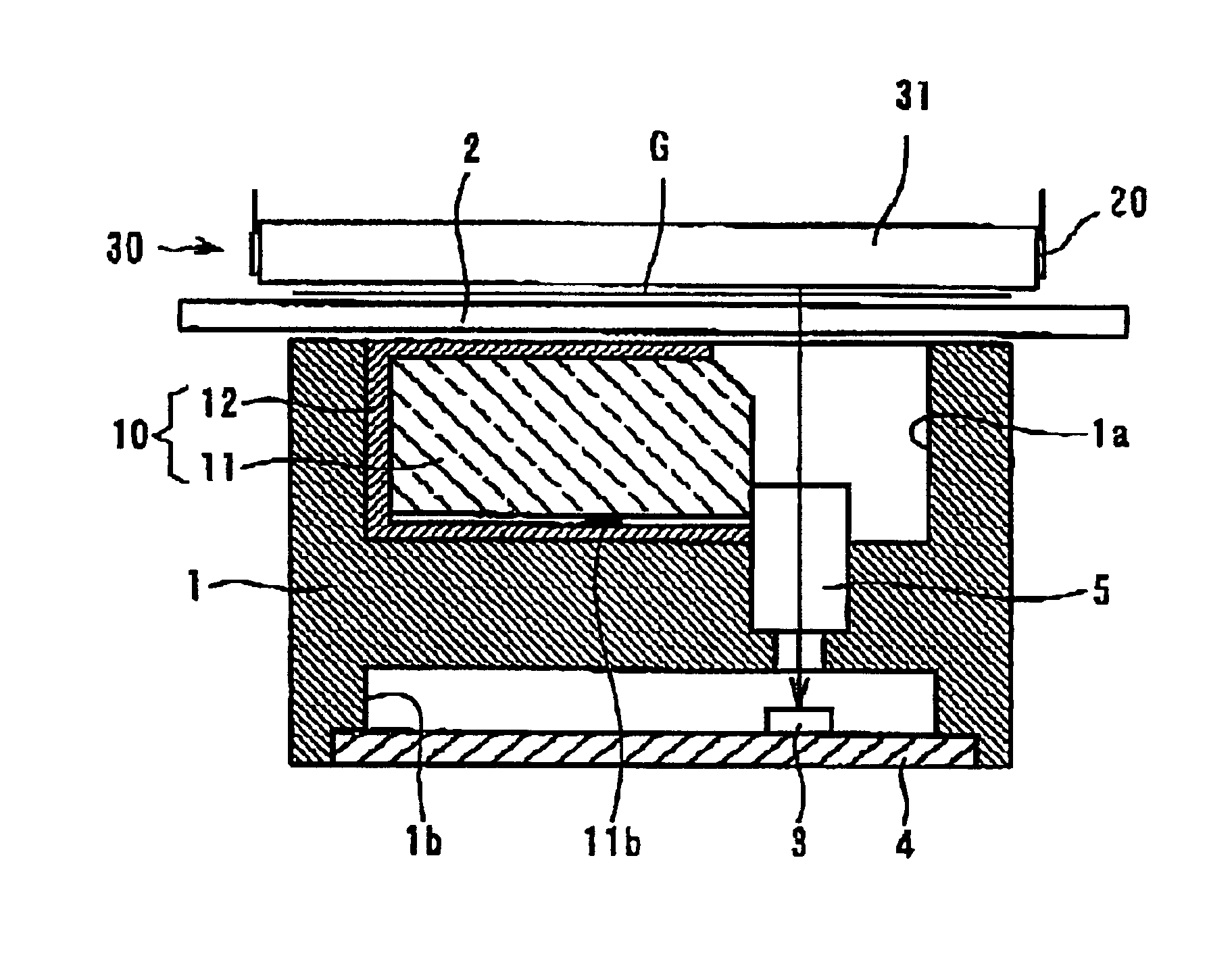
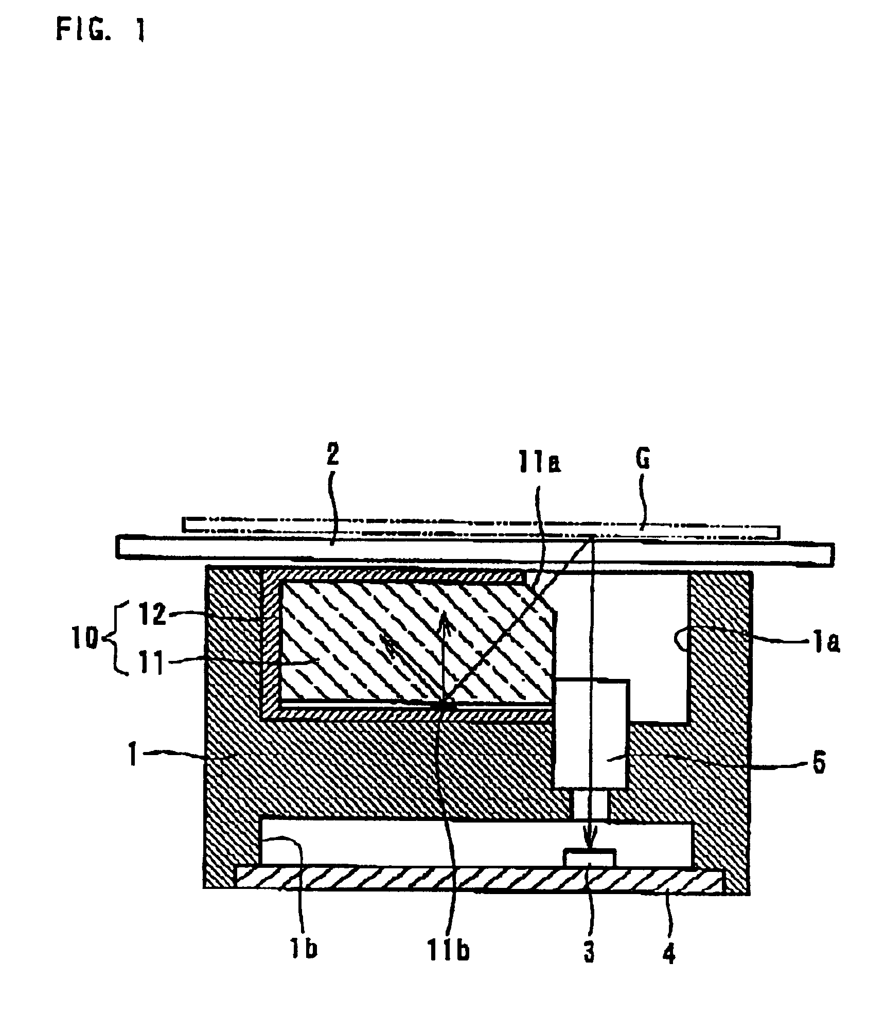
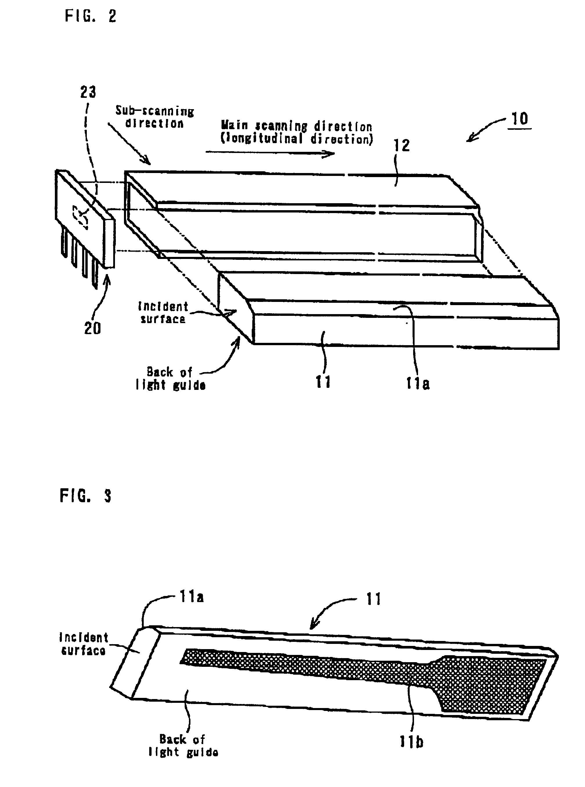
[0048]A preferred embodiment of the present invention will now be described with reference to the accompanying drawings. As shown in FIG. 1, an image reading device is provided, in which a frame 1 is provided with depressions 1a and 1b. A line illumination device 10 is disposed within the depression 1a, and a sensor board 4 provided with a photoelectric conversion element (i.e., a line image sensor) 3 is disposed within the depression 1b. A rod lens array 5 for 1:1 image formation is also held within the frame 1. Provided above the frame 1 is a glass plate 2. Light emitted from a light-emitting surface 11a of the line illumination device 10 is projected onto a document G through the glass plate 2. The reflected light from the document G is then detected by the photoelectric conversion element (i.e., the image sensor) 3 through the rod lens array 5 to read the document G. The frame 1 is moved in a sub-scanning direction shown in FIG. 2 relative to the glass plate 2 to read a desired ...


PUM


Abstract

A light-emitting unit 20 has a light-emitting unit board 21 made of resin provided with a lead frame 22. The light-emitting unit board 21 is also provided with an open window 21a for mounting a light-emitting device. The lead frame 22 comprises a lead terminal section 22a, an inner lead section 22c, and a light-emitting device mounting and connecting section 22b which is exposed within the open window 21a. The light-emitting devices 23a, 23b, and 23c are bonded with the light-emitting device mounting and connecting section 22b, and electrodes of the light-emitting devices and the lead frame are connected by a metal wire 24, wherein the open window 21a is sealed by transparent resin. The lead frame 22 is made of iron-containing copper to improve heat radiation performance of the light-emitting unit board. By increasing maximum current to be supplied to the light-emitting diodes, it is possible to increase illumination brightness and to attain speedup of image reading.

Description

BACKGROUND OF THE INVENTION[0001]1. Field of the Invention[0002]The present invention relates to a light-emitting unit, an illumination device for illuminating a document, and a contact-type image reading device (i.e., an image sensor) incorporating the illuminating device therein.[0003]2. Description of the Prior Art[0004]A contact-type image sensor is used as a device for reading a document using facsimile terminal equipment, a copying machine, an image scanner, etc. This contact-type image sensor is provided with a line illumination device for linearly illuminating a document surface over a main scanning range.[0005]The line illumination device using a light guide is known and disclosed, for example, in Japanese Unexamined Patent Publication No. HEI 8-163320 (1996) and Japanese Unexamined Patent Publication No. HEI 10-126581 (1998) (Japanese Patent No. 2999431) in which the line illumination device using a bar-shaped or plate-shaped light guide and an image reading device using s...

Claims


Application Information

Patent Timeline
Patent Type & Authority Patents(United States)
IPC IPC(8): H04N1/028H04N1/40
CPCH04N1/02815H04N1/02835H04N1/02885H04N1/0318H04N1/40056H04N1/0282Y10S362/80H04N2201/02462H04N2201/02495H04N2201/03112H04N2201/02485H04N2201/03158H04N2201/04767
Inventor UEMURA, YOSHIYUKISAITO, TOMIHISA
Owner NIPPON SHEET GLASS CO LTD
Why Eureka
Try Eureka