Method for laser welding of metal

a laser welding and metal technology, applied in the direction of welding apparatus, manufacturing tools, transportation and packaging, etc., can solve the problems of poor weld surface conditions such as undercutting, underfilling and voids, and excessive spatter

Inactive Publication Date: 2005-06-14
METALSA SA DE CV
View PDF20 Cites 28 Cited by
  • Summary
  • Abstract
  • Description
  • Claims
  • Application Information

AI Technical Summary

Problems solved by technology

The vapor pressure expands out through the molten base metal created by the laser beam and results in weld porosity, excessive spatter and poor weld surface conditions such as undercut, underfill and voids.
These conditions can cause failures in the weld at a later point in time.
If two thus protected metal sheets using a material such as zinc or a similar material are welded together using the same technique employed for welding bare sheet, the resulting welds invariably prove uneven and riddled with craters, faults which, involve high-cost follow-up machining for their removal.
While the aforementioned method has proved particularly effective for welding bare sheet steel with and without the addition of filler metal, which attaches to the area proximate with the joint between the two sheets of steel to build a weld seam, it is not particularly effective for sheets of material that are coated with some protective layers as mentioned above.
This method proves inadequate when welding together metal sheets protected against external agents by using a layer of coating of low-vaporizing-temperature materials.
Thus, the prior art fails to provide adequate disclosure of the relationship of the sheet shape and the weld location relative to the physical characteristics of the sheets.

Method used


Image

  • Method for laser welding of metal
  • Method for laser welding of metal
  • Method for laser welding of metal

Examples


Embodiment Construction

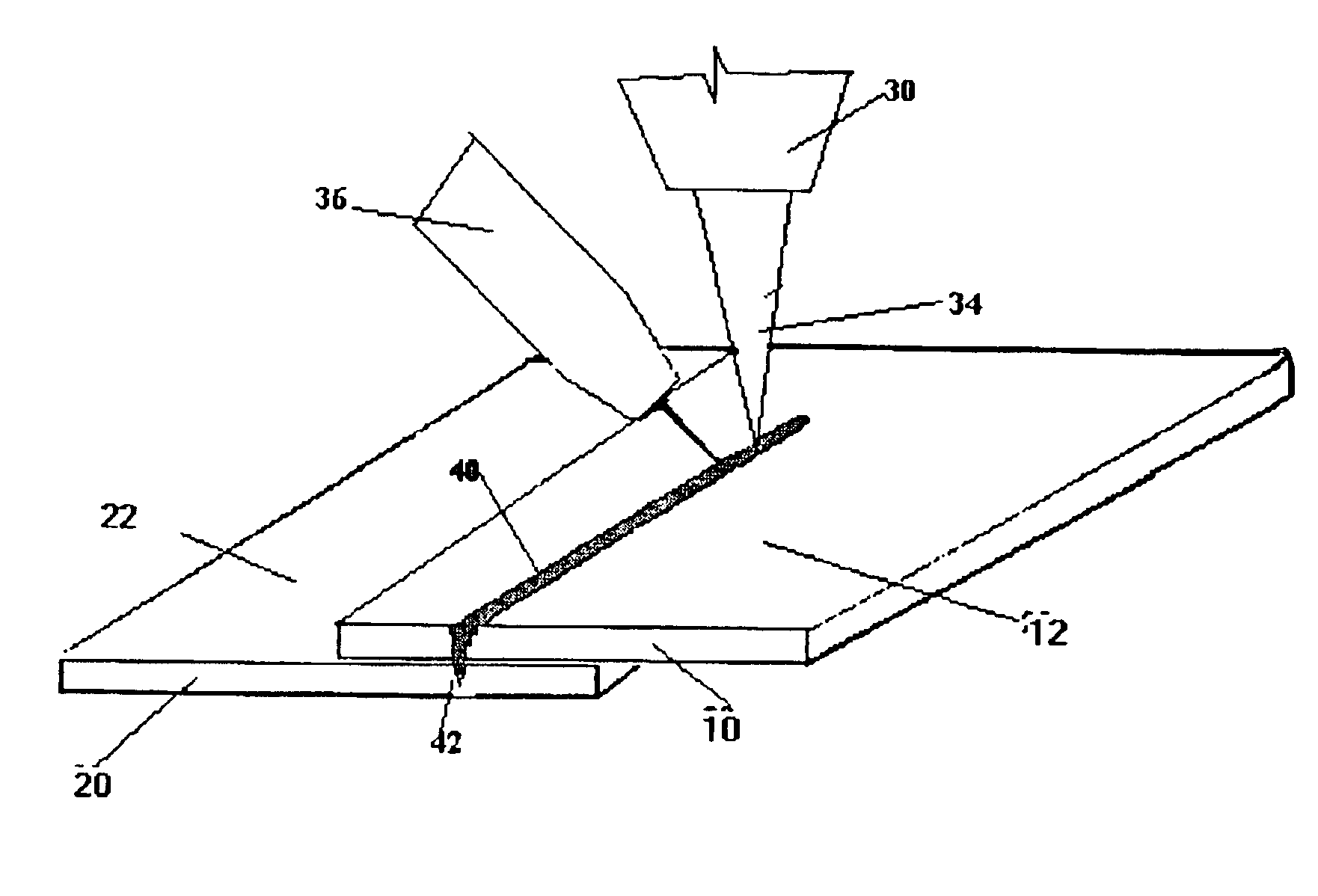
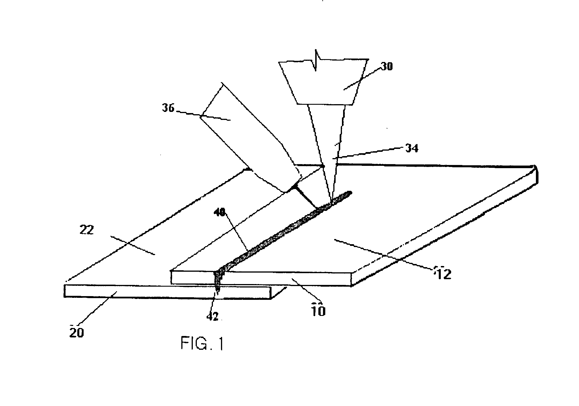
[0023]As shown in FIG. 1., a first sheet of metal 10 is to be joined with a second sheet of metal 20. The first sheet of metal 10 is arranged on top of the second sheet of metal 20. Both the first sheet of metal 10 and the second sheet of metal 20 include a protective layer 12, 22 made of a low-vaporizing-temperature material. One example of such a material is zinc.

[0024]While FIG. 1 indicates that metal sheet 10 and metal sheet 20 are separate sheets, it should be appreciated that for the purposes of this invention, the two metal sheets may also consist of a single sheet bent or wrapped to resemble some form of a U-shape.

[0025]Furthermore, the attached drawings illustrate that a single protective layer 12, 22 is provided on the top surface of both metal sheets 10, 20. Typical thickness for a protective layer of zinc placed onto a metal sheet ranges from zero to approximately 7.5 microns.

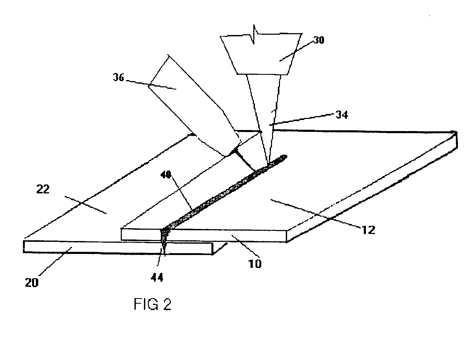
[0026]The particular location of the protective layers 12 and 22 as indicated in FIGS. 1 and 2 b...


PUM

PropertyMeasurementUnit
thicknessaaaaaaaaaa
temperatureaaaaaaaaaa
pressureaaaaaaaaaa

Abstract

A method of welding at least two metal sheets protected by a zinc coating that has a low vaporizing temperature. The metal sheets are placed on top of each other and a head of a welding machine is passed over the sheets. The head of the welding machine is configured such that a laser is positioned in front of a GMAW welding or MIG brazing device. The laser cuts a channel into the metal sheets in order to allow the protective zinc coating to vaporize and escape. The GMAW welder or MIG brazing device then follows the laser and deposits a material that fills the channel to weld the two pieces together.

Description

BACKGROUND OF THE INVENTION[0001]1. Field of the Invention[0002]The present invention relates to a method for a hybrid laser welding multiple sheets of steel together. More particularly, the present invention relates to a method for performing a laser beam welding operation for joining steel stampings to hydroformed parts using a single penetrating lap joint design.[0003]2. Description of Related Art[0004]Conventionally, laser beam machines are known to be employed, not only for cutting flat or otherwise drawn sheet metal along given cutting lines, but also for spot or seam welding sheets together. The sheets may be either steel stampings or hydroformed parts which may or may not be coated with a protective layer, such as zinc, on the surface.[0005]During laser welding, the energy from the laser beam penetrates through the first piece into the second piece of steel, heating portions of the two pieces to a sufficiently high temperature so that they melt and coalesce together to form ...

Claims


Application Information

Patent Timeline
Patent Type & Authority Patents(United States)
IPC IPC(8): B23K26/32B23K26/14B23K28/02B23K28/00B23K26/00B23K26/24B23K9/173B23K9/23B23K9/16B23K26/20B23K103/04B23K103/16
CPCB23K1/00B23K9/16B23K9/167B23K26/3293B23K26/1429B23K26/246B23K26/3206B23K26/0093B23K26/32B23K26/244B23K26/348B23K2101/34B23K2103/08B23K2103/50B65H75/243B65H18/04B65H2301/4136
Inventor MUSSELMAN, GARY H.
Owner METALSA SA DE CV
Why Eureka
Try Eureka