Integrated tessellator in a graphics processing unit

a graphics processing unit and integrated technology, applied in the field of graphics pipeline systems, can solve the problems of computational intensive process of rendering and displaying a three-dimensional object, limited computations needed to realistically render and display a three-dimensional graphical object, and limited true realistic display of three-dimensional objects, so as to achieve the effect of improving quality and improving performan

Inactive Publication Date: 2005-06-14
NVIDIA CORP
View PDF15 Cites 69 Cited by
  • Summary
  • Abstract
  • Description
  • Claims
  • Application Information

AI Technical Summary

Benefits of technology

[0015]With the foregoing integration, improved performance is achieved thus overcoming many of the shortcomings of non-integrated systems. For example, the combined tessellation and transform integration affords improved quality by way of finer tessellations. Applications can thus take advantage of this and other capabilities by invoking the corresponding feature associated with the single semiconductor platform via a standard interface.

Problems solved by technology

The amount of computations needed to realistically render and display a three-dimensional graphical object, however, remains quite large and true realistic display of three-dimensional objects have largely been limited to high end systems.
Thus the process of rendering and displaying a three-dimensional object can be computationally intensive and may involve a large number of vertices.
For example, the quality of computer graphics is currently limited by the ability of the graphic pipeline to execute transform operations.
This creates a classic performance-versus-quality trade-off for the software developer because finer tessellation will result in more polygons and slower performance, but with the reward of higher quality.
Integration is often limited, however, by a cost of implementing and manufacturing multiple processing modules on a single chip.
In the realm of graphics processing, any attempt to integrate the various modules for increased speed would be cost prohibitive.
The reason for this increase in cost is that the required integrated circuit would be of a size that is simply too expensive to be feasible.
This size increase is due mainly to the complexity of the various engines.
High performance transform and lighting engines alone are very intricate and are thus expensive to implement on-chip, let alone implement with any additional functionality.
Further, conventional rasterizers are multifaceted with the tasks of clipping, rendering, etc. making any cost-effective attempt to combine such module with the transform and lighting modules nearly impossible.

Method used


Image

  • Integrated tessellator in a graphics processing unit
  • Integrated tessellator in a graphics processing unit
  • Integrated tessellator in a graphics processing unit

Examples


Embodiment Construction

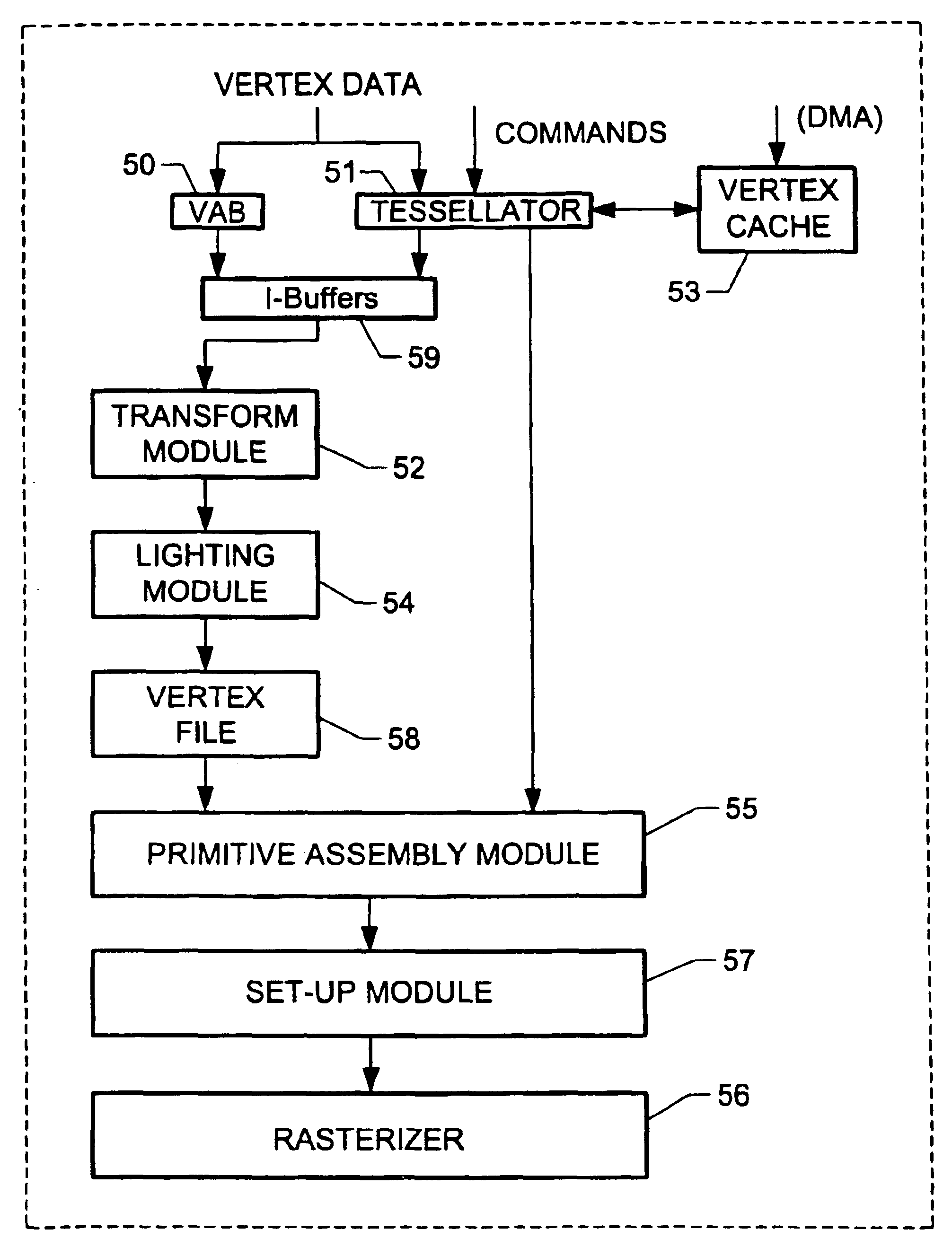
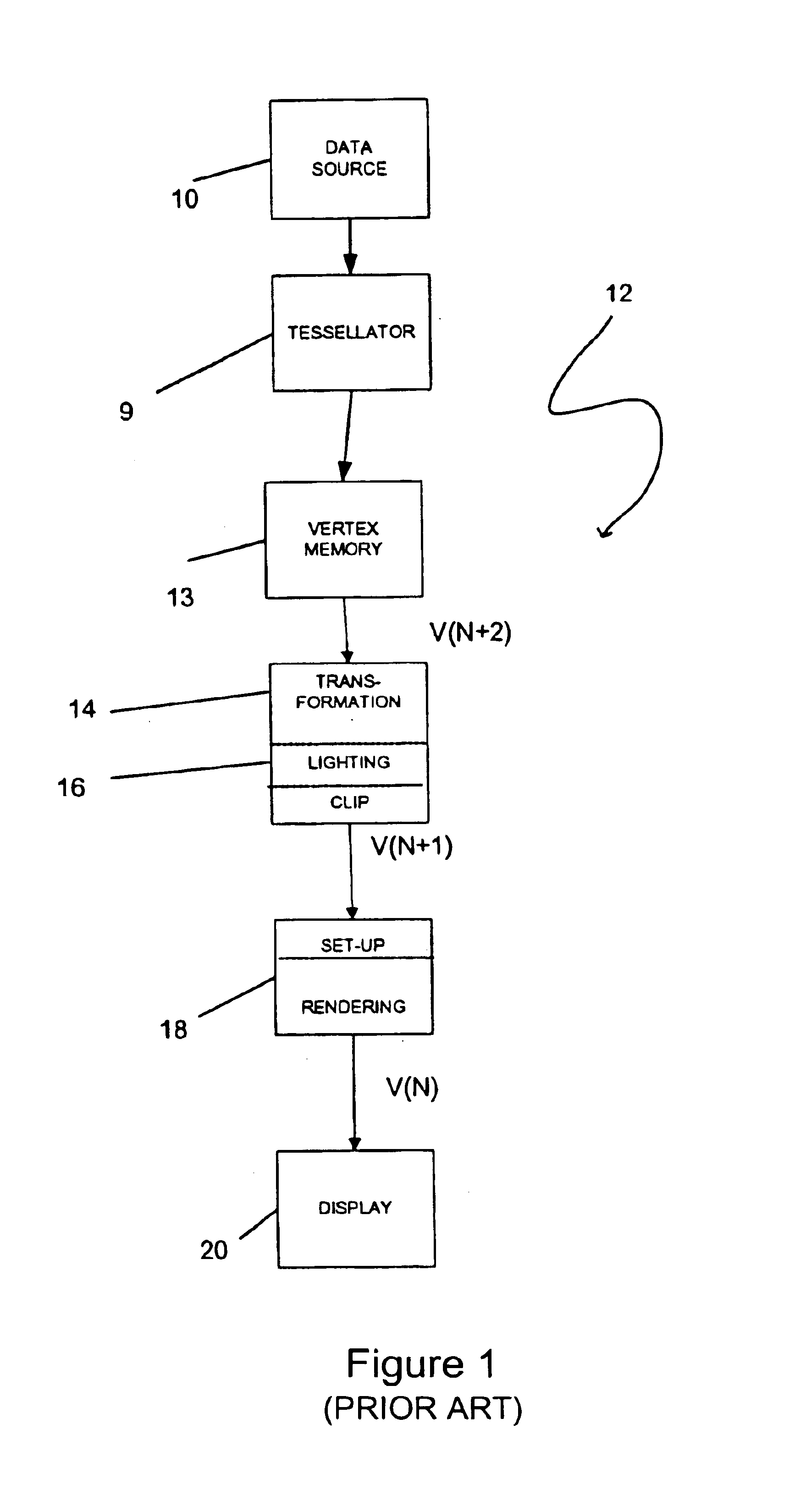
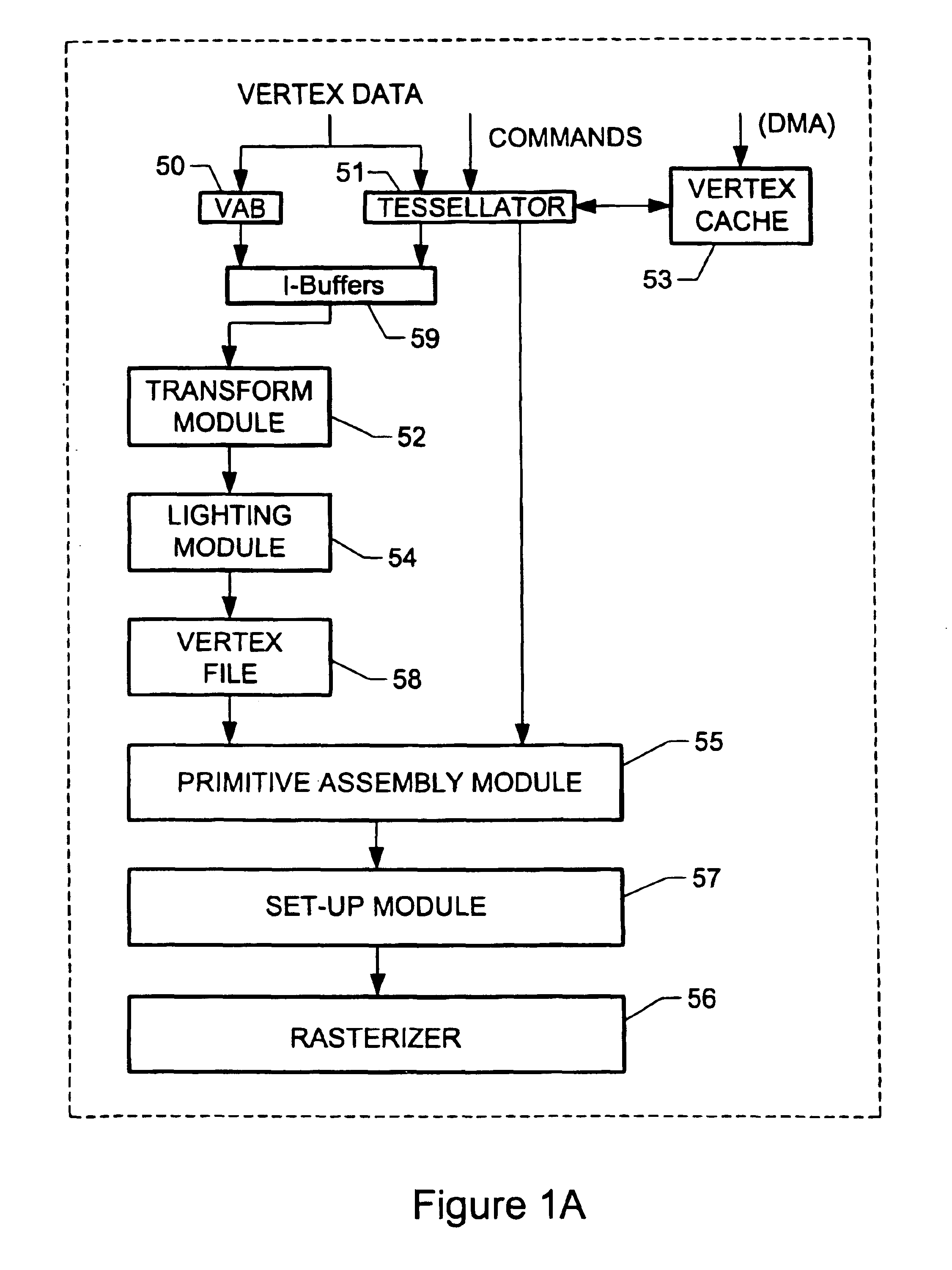
[0075]FIG. 1 shows the prior art. FIG. 1A is a flow diagram illustrating the various components of one embodiment of the present invention. FIG. 1A illustrates a single-chip implementation of a graphics processing pipeline which incorporates a tessellation module 51. As shown, the tessellation module 51 receives as input data, i.e. vertex data, geometric descriptions, etc., and commands. Further, a vertex cache 53 populated using direct memory access (DMA) capabilities is provided which also feeds the tessellation module 51. When the tessellation module 51 is enabled, tessellated data is outputted from the tessellation module 51 to I-Buffers 59 which also receive data, i.e. vertex data, from a vertex attribute buffer (VAB) 50. Such I-Buffers 59 work to feed a transform module 52 and lighting module 54. The transform and lighting modules subsequently feed output to a vertex file 58. Also shown in FIG. 1A is a primitive assembly module 55 which communicates with the vertex file 58 and...


PUM


Abstract

An integrated graphics pipeline system is provided for graphics processing. Such system includes a tessellation module that is positioned on a single semiconductor platform for receiving data for tessellation purposes. Tessellation refers to the process of decomposing either a complex surface such as a sphere or surface patch into simpler primitives such as triangles or quadrilaterals, or a triangle into multiple smaller triangles. Also included on the single semiconductor platform is a transform module adapted to transform the tessellated data from a first space to a second space. Coupled to the transform module is a lighting module which is positioned on the single semiconductor platform for performing lighting operations on the data received from the transform module. Also included is a rasterizer coupled to the lighting module and positioned on the single semiconductor platform for rendering the data received from the lighting module.

Description

RELATED APPLICATIONS[0001]The present application is a continuation application of application entitled “Integrated Tessellator in a Graphics Processing Unit” which was filed Nov. 21, 2000 under Ser. No. 09 / 718,890 now U.S. Pat. No. 6,597,356, which is a continuation-in-part of applications entitled “System, Method and Article of Manufacture for Decomposing Surfaces using Guard Curves and Reversed Stitching” which was filed Aug. 31, 2000 under Ser. No. 09 / 652,866 now U.S. Pat. No. 6,624,811; “System, Method and Article of Manufacture for Fractional Tessellation during Graphics Processing” which was filed Sep. 5, 2000 under Ser. No. 09 / 655,103 now U.S. Pat. No. 6,504,537; and “System, Method and Article of Manufacture for Rendering Triangular Patches using Hardware Equipped for Handling Quadrilateral Patches” which was filed Sep. 5, 2000 under Ser. No. 09 / 655,105 now U.S. Pat. No. 6,704,010, and which are all incorporated herein by reference in their entirety. The present application...

Claims


Application Information

Patent Timeline
Patent Type & Authority Patents(United States)
IPC IPC(8): G06T17/20G06T15/00
CPCG06T15/005G06T17/205G06T17/20
Inventor MORETON, HENRY P.LEGAKIS, JUSTINROGERS, DOUGLAS H.
Owner NVIDIA CORP
Why Eureka
Try Eureka