
System and method for recovering phase information of a wave front

a wave front and phase information technology, applied in the field of system and method for recovering phase information of wave fronts, can solve the problems of low error value, computational intensive prior art methods in trying to distinguish between these slight phases

Inactive Publication Date: 2005-06-14
WAVEFRONT ANALYSIS
View PDF6 Cites 33 Cited by
  • Summary
  • Abstract
  • Description
  • Claims
  • Application Information

AI Technical Summary

Benefits of technology

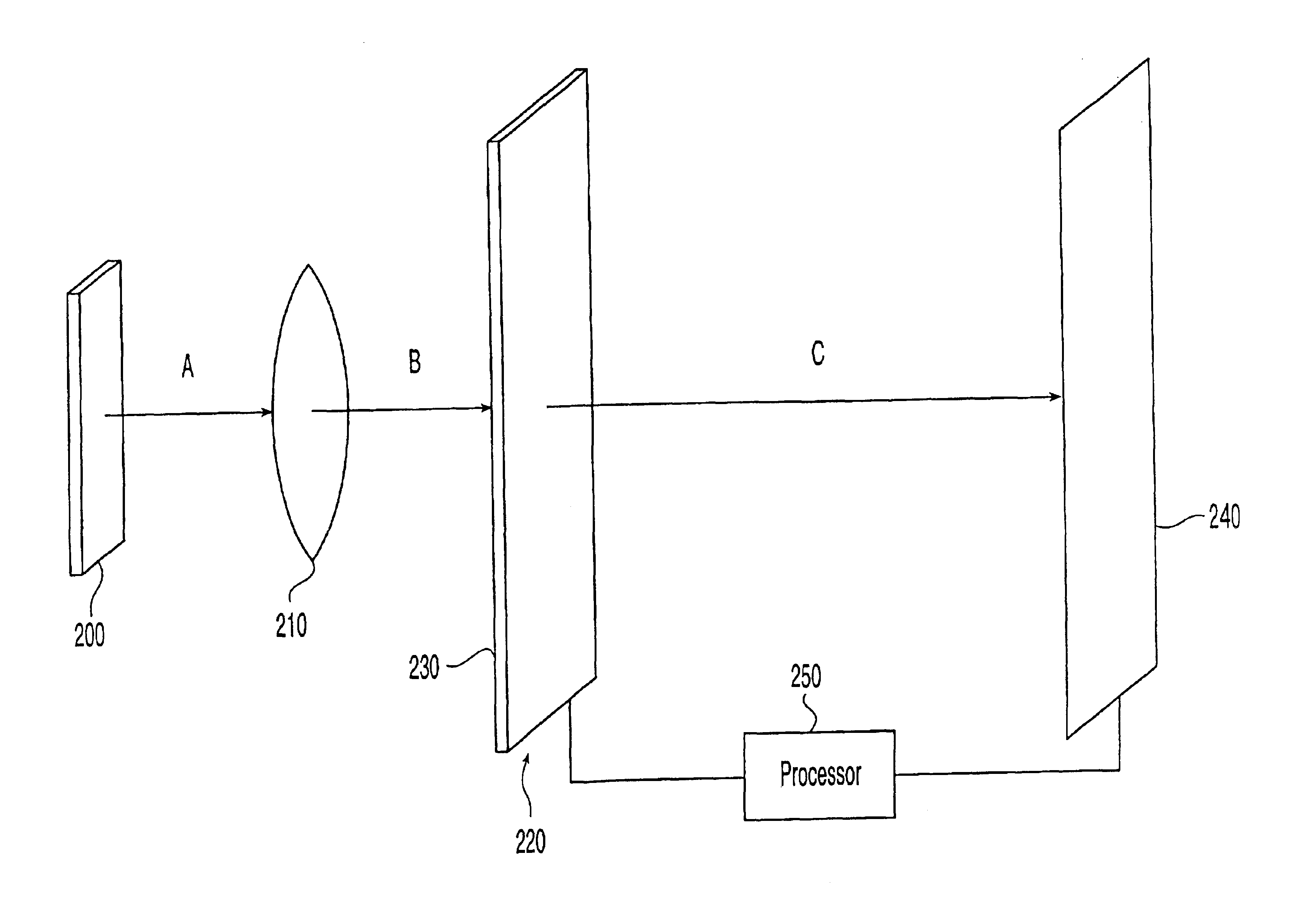
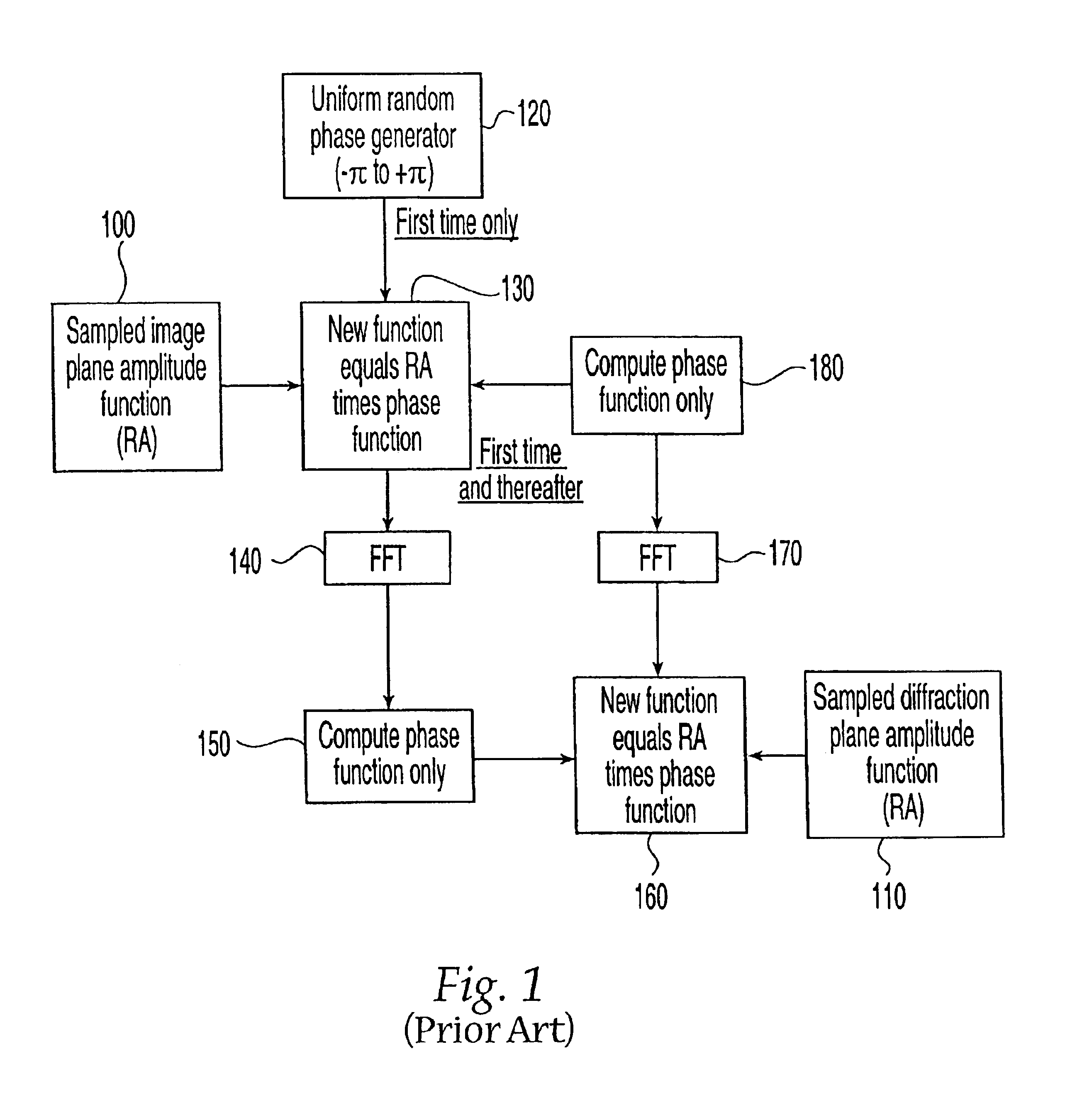
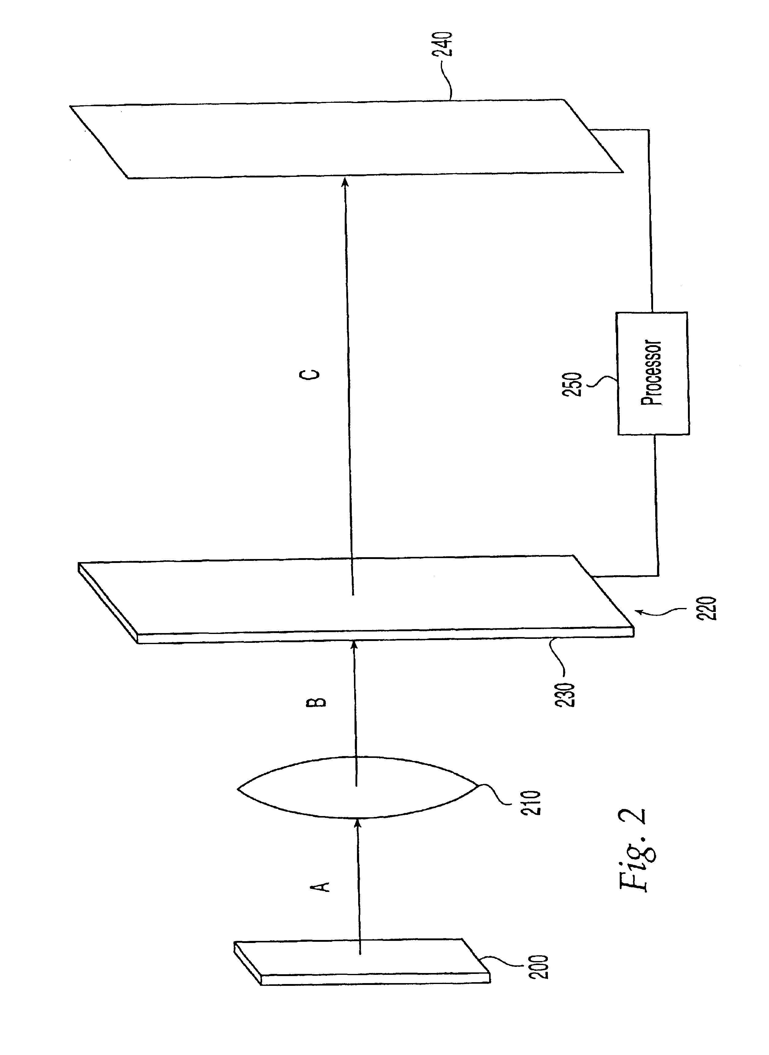
[0012]The present invention is driven by an “error reduction” principle and requires a plurality of samples of the wave front from the object being observed. In one aspect, the invention relies on the fact that the back focal plane of a convergent lens on which the scattered wave from the object impinges contains a wave function, which is directly proportional to the Fourier Transform of the object and is therefore directly proportional to the Fourier Transform of the image plane wave function of the object. In the case where the phase difference from one pixel to any of its neighboring pixels only changes slightly, prior art methods were computationally intensive in trying to distinguish between these slight phase differences. Since the actual back focal plane (BFP) wave transforms to the true image in the Image Plane, by the intervention of the drift space between these two planes (mathematically causing the BFP wave to undergo Fourier Transformation yielding the Image Plane wave), in accordance with the invention a very useful relationship is obtained between the measurements in these two conjugate planes. However, other relationships between the waves in these two planes are achievable by changing the phase and / or amplitude distribution in the BFP. In one aspect of the invention, this can be accomplished by using known but physically different phase filters, in the BFP, whose effects on the BFP phase distribution are known. It is noted that there are other physical methods of effectively changing the phase in the BFP (e.g., the use of defocus). The Image Plane wave resulting from this intervention can be very different from the true object wave, consequently yielding new relationships between intensity measurements in these two conjugate planes. The present invention uses several of these new “synthesized” relationships to drastically reduce computation of the reconstructed wave form, to avoid stagnation in the iterating algorithm, and to avoid certain well known ambiguities in the reconstructed wave function.

Problems solved by technology

In the case where the phase difference from one pixel to any of its neighboring pixels only changes slightly, prior art methods were computationally intensive in trying to distinguish between these slight phase differences.
This correction results in an error value.

Method used


Image

  • System and method for recovering phase information of a wave front
  • System and method for recovering phase information of a wave front
  • System and method for recovering phase information of a wave front

Examples


Embodiment Construction

[0040]The present invention generally applies to propagating wave fronts, along whose path of propagation two planes exist in which the complex wave distributions are related by a transform, which generally would be linear, invertible and energy conservative, such as a Fourier transform. These two planes will also be referred to as conjugate planes. Such conjugate planes exist, for example, between an electromagnetic antenna aperture and its far field (Fraunhofer) plane, or between the object plane and the back focal plane of a convergent lens imaging the object plane, or between the back focal plane of a light camera's objective lens and the camera's image plane, or between the diffraction and the image planes of a transmission electron microscope, or between an X-ray illuminated crystal structure and its diffraction plane, and so on. Given that the ability of recording media is limited to recording only the intensity distribution in these planes, the need arises to recover the pha...


PUM


Abstract

A system and method for recovery of phase information from recorded intensity values is disclosed. In one aspect, a phase filter is placed in a plane, which may be the back focal plane (BFP) of a lens used for observing an object. The phase filter changes the phase of a wave front distribution in the BFP in a known manner. Amplitude stops or combinations of phase and amplitude filtering patterns can also be used to capture N different sets of intensity data in a conjugate diffraction plane. The N intensity images are used to obtain an estimate of the wave front at the first plane. This wave front estimate is then used to generate N modified estimates of the wave front at the conjugate plane, each modified estimate corresponding to one of N filtering patterns. In one implementation, the N modified IP estimates are corrected by replacing the estimated amplitudes with the actually measured ones for that image. The process is repeated iteratively until an error measure between the measured values and the synthetically generated ones falls below a known threshold. The resulting phase estimates can be used to display wave front information similar in appearance to holograms, or to create lens-free microscopes.

Description

[0001]This is a division of Ser. No. 09 / 858,943 filed on May 16, 2001 now U.S. Pat. No. 6,545,790, which is a continuation-in-part of application Ser. No. 09 / 708,290 filed Nov. 8, 2000 now U.S. Pat. No. 6,369,932, which converted from provisional application No. 60 / 163,978, filed Nov. 8, 1999.FIELD OF THE INVENTION[0002]The present invention is generally directed to a system and method for recovering wave front phase information and using the recovered information. More particularly, the invention is directed to a system and method for determining the phase information associated with a wave front from measured intensity information.BACKGROUND OF THE INVENTION[0003]Huygens, Kirchhoff, Sommerfield and Rayleigh originated and contributed most to the currently accepted theory of diffraction, which forms the theoretical foundation for the present invention. Basically, the theory postulates that given a known wave front filling a planar window in an otherwise dark planar screen, the wave...

Claims


Application Information

Patent Timeline
IPC IPC(8): G02B27/46
CPCG02B27/46G03H1/0808G03H2001/0816G03H2001/0454
Inventor GERCHBERG, RALPH W.
Owner WAVEFRONT ANALYSIS
Learn More