Burst signal detection circuit

a detection circuit and burst signal technology, applied in pulse technique, dc level restoring means or bias distort correction, baseband system details, etc., can solve the problems of erroneously detecting the amplitude of the input signal, adverse effect of burst signal detection, etc., and achieve high accuracy

Inactive Publication Date: 2005-06-14
FUJITSU LTD
View PDF8 Cites 58 Cited by
  • Summary
  • Abstract
  • Description
  • Claims
  • Application Information

AI Technical Summary

Benefits of technology

[0020]An object of the present invention is to provide a burst signal detection circuit for detecting a burst signal with high accuracy against the DC level

Problems solved by technology

In the case where burst signals having considerably different amplitudes are input continuously to the photodiode, however, the problem described below arises.
However, the DC level variation is large and is not negligible for the second burst signal (packet #2) having a small amplitude, and has an adverse effect on the burst signal detection.
Specifically, the problem arises in the

Method used


Image

  • Burst signal detection circuit
  • Burst signal detection circuit
  • Burst signal detection circuit

Examples


first embodiment

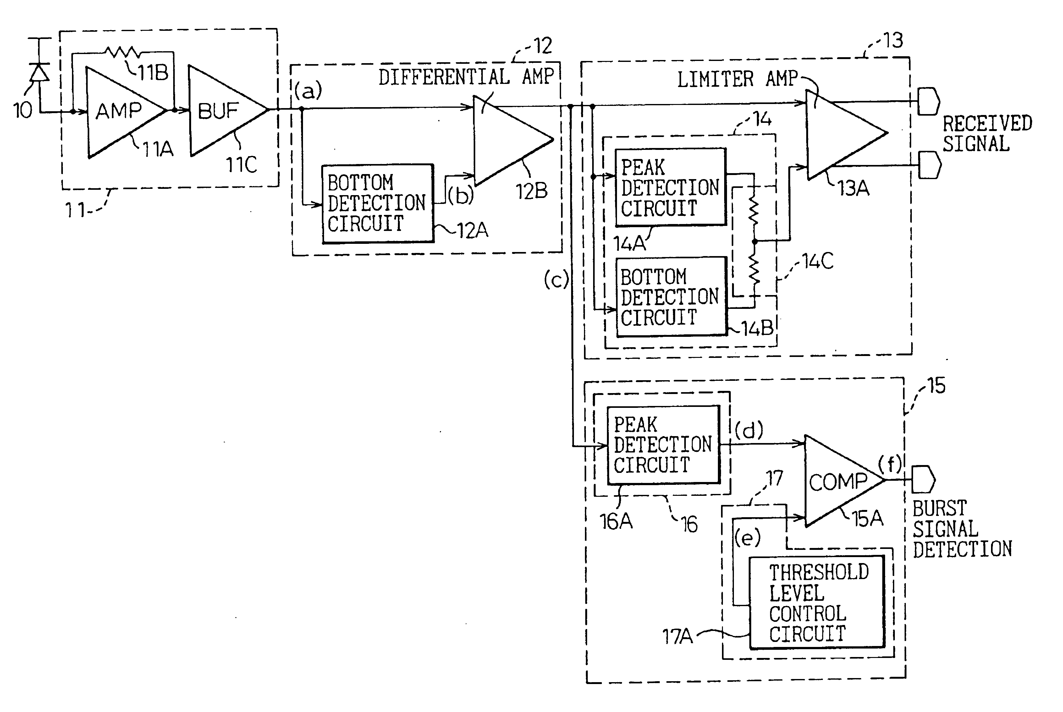
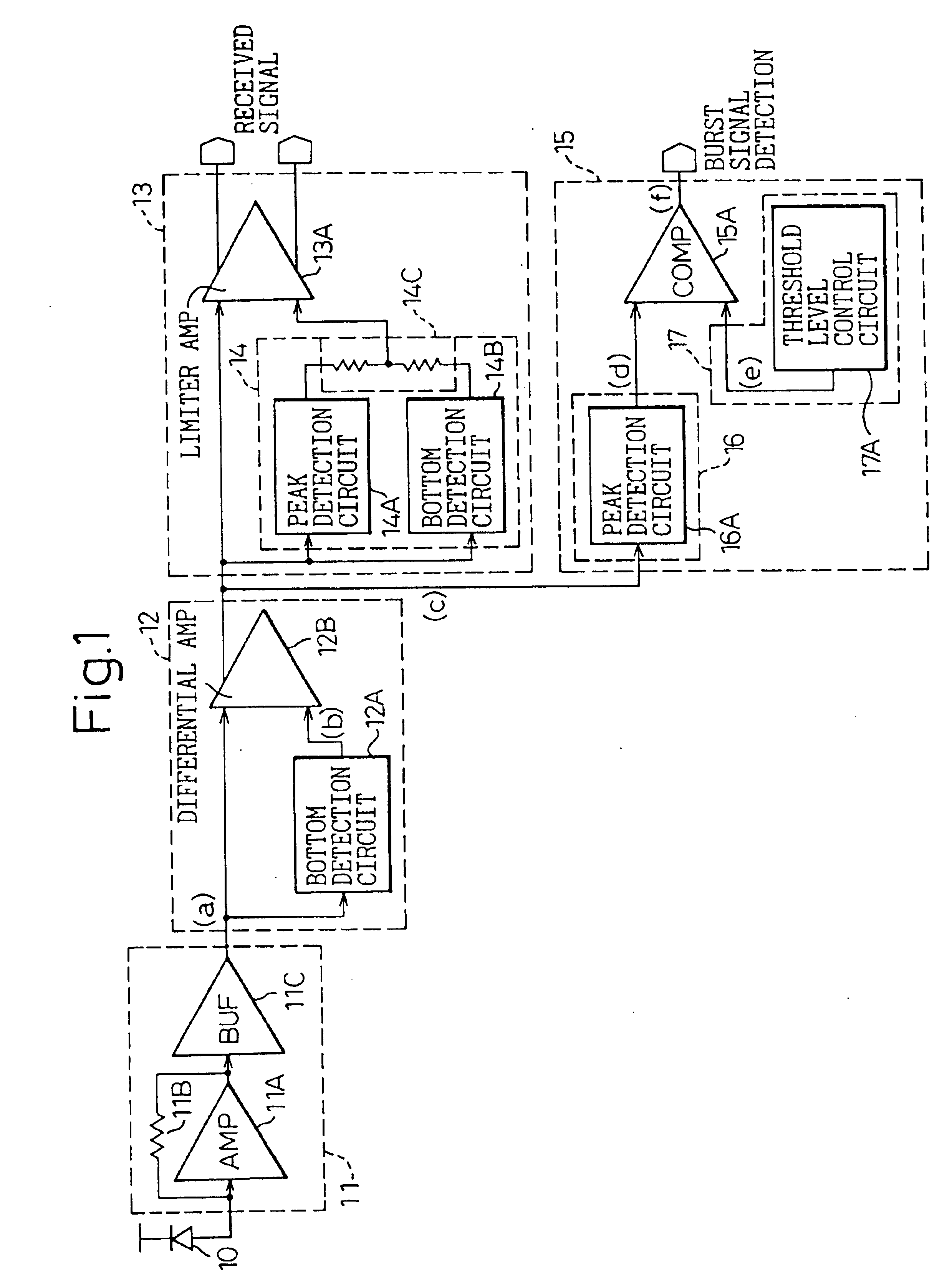
[0064]FIG. 1 shows a configuration of the invention. FIGS. 2A to 2C show operating waveforms of the same embodiment. In FIG. 1, a burst signal detection circuit for an optical burst signal receiver is shown. In the figure, reference numeral 10 designates a photo-diode (PD), numeral 11 a preamplifier, numeral 12 a DC variation removing circuit, numeral 13 a signal amplifier, numeral 14 an automatic threshold control (ATC) circuit, numeral 15 an amplitude identifying circuit, numeral 16 an amplitude detection circuit and numeral 17 a identifying circuit.

[0065]The photo-diode (PD) 10 converts the arriving optical signal into a current signal, and the preamplifier 11 converts the current signal output from the photo-diode (PD) 10 into a voltage signal by means of an amplifier 11A, a resistor 11B and an inverting buffer amplifier 11C.

[0066]The DC variation removing circuit 12 applies the output signal of the preamplifier 11 to the bottom detection circuit 12A and the differential amplifi...

third embodiment

[0091]Also, the amplitude detection circuit 56 in the amplitude identifying circuit 55 includes the peak detection circuit 16A and a bottom detection circuit 56B for detecting both a peak level and a bottom level.

[0092]By means of the threshold level control circuit 57A providing a predetermined current and a resistor 57B, the threshold level in the amplitude identifying circuit 55 is generated by shifting a predetermined voltage from the bottom level detected by the bottom detection circuit 56B in the amplitude detection circuit 56.

[0093]In the first embodiment described above, since the amplitude detection circuit 16 detects the level of only one side (peak side), the output level is affected by the DC operating point of the differential amplifier 12B. In the third embodiment, in contrast, since the threshold level is generated by shifting to the bottom level, the amplitude component alone can be detected without being affected by the DC operating point.

[0094]FIGS. 6A to 6C show ...

fourth embodiment

[0108]FIGS. 9A to 9C show operating waveforms according to the FIG. 9A shows a waveform of the output signal from the DC variation removing signal amplifier 83, FIG. 9B a waveform in each circuit of the amplitude identifying circuit 85, and FIG. 9C a waveform of the comparator 85A in the amplitude identifying circuit 85.

[0109]To the DC variation removing signal amplifier 83, a signal (a) indicated by a dotted line in FIG. 9A is input, and the bottom detection circuit 83A in the DC variation removing signal amplifier 83 outputs a detected bottom level (b) indicated by a solid line in FIG. 9C.

[0110]The detected bottom level (c) is input to one input terminal of the amplifier 84A through a resistor 84D. To the input terminal, the peak level detected by the peak detection circuit 84B from the positive phase output of the amplifier 84A is also input. As a result, a level in the vicinity of the central portion of the received signal level is determined as a threshold level.

[0111]To the o...


PUM


Abstract

A burst signal detection circuit for detecting the arrival of a burst-like signal, which can accurately detect the burst signal against the DC level variations even in the case where the arriving burst signal is a weak signal, is disclosed. A DC variation removing circuit detects the bottom level of an input signal and removes the DC level variation of the input signal based on the bottom level. An amplitude identifying circuit detects the presence or absence of a burst signal based on the output signal of the DC variation removing circuit. The amplitude identifying circuit includes an amplitude detection circuit for detecting the maximum amplitude of the output signal of the DC variation removing circuit, a threshold level control circuit for controlling the threshold level and a comparator for comparing the output level of the amplitude detection circuit with the threshold level and outputting a detection signal indicating the presence or absence of a burst signal.

Description

BACKGROUND OF THE INVENTION[0001]1. Field of the Invention[0002]The present invention relates to a burst signal detection circuit for detecting the arrival of a burst-like signal, and in particular to a burst signal detection circuit used most suitably for a transmission system for transmitting a high-speed optical burst signal in a system such as a passive optical network (PON) system used in a transmission for optical subscriber system.[0003]2. Description of the Related Art[0004]In the transmission of an optical burst signal, the timing of sending out the burst signal to be transmitted is not definitely determined, and therefore a burst signal detecting signal is required to notify the arrival of the burst signal to the transmission system.[0005]For configuring a flexible network system in which each terminal unit for sending out the burst signal can be accommodated at an arbitrary position on the network and a restriction on the transmission distance is relaxed, it is necessary ...

Claims


Application Information

Patent Timeline
IPC IPC(8): H04B10/02H04L25/03H04B10/00H04L25/06H03G3/30H04B10/40H03K5/08H04B10/07H04B10/2507H04B10/50H04B10/60
CPCH03G3/3084H04B10/695H04B10/6933H03K5/082
Inventor IDE, SATOSHISAKURAMOTO, SHINICHI
Owner FUJITSU LTD
Why Eureka
Try Eureka