

Anisotropic scattering film and liquid crystal display using the same
a technology of anisotropic scattering and liquid crystal display, which is applied in the direction of instruments, other domestic objects, transportation and packaging, etc., can solve the problems of unsatisfactory scattering strength, difficult control of particle dispersibility, and inability to obtain scattering strength, etc., to achieve excellent scattering property, high luminance, and high transmittance
- Summary
- Abstract
- Description
- Claims
- Application Information
AI Technical Summary
Benefits of technology
Problems solved by technology
Method used
Image

Examples
example 1
[0098]First, a polymerization method of LCP is shown below.
(1) Melt Polymerization
[0099]A 50 liter SUS polymerization vessel having an anchor type stirring blade whose distance of the vessel wall and the stirring blade is short was used. Into this polymerization vessel were charged 20.45 kg (113.5 mol) of p-acetoxybenzoic acid, 1.26 kg (7.6 mol) of terephthalic acid, 5.04 kg (30.4 mol) of isophthalic acid and 10.22 kg (37.8 mols) of 4,4′-diacetoxydiphenyl heated with an oil circulating heating apparatus under nitrogen flow. From the time when the heating medium became to 150° C., the temperature was raised gradually to about 300° C. at a heating rate of about 0.7° C. / minutes, acetic acid by-produced during the polycondensation reaction was removed continuously. The temperature of the heating medium was kept at 300 to 310° C., and after 1 hour, sampling was conducted, and the flow temperature was measured to be 235° C.
[0100]The reaction was continued further for 1 hour, and the stirr...
example 2
[0111]A film was produced as the same manner with Example 1, except that an alicyclic polyolefin resin (ARTON G, produced by JSR, Tg 171° C.; hereinafter may be referred to as ARTON) was used as the resin material for matrix phase.
(Micro-Structure Observation)
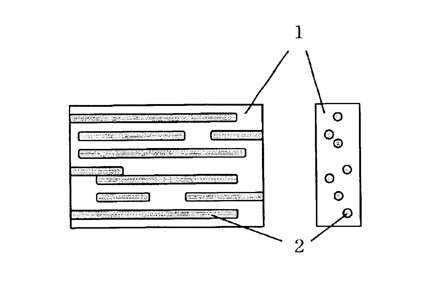
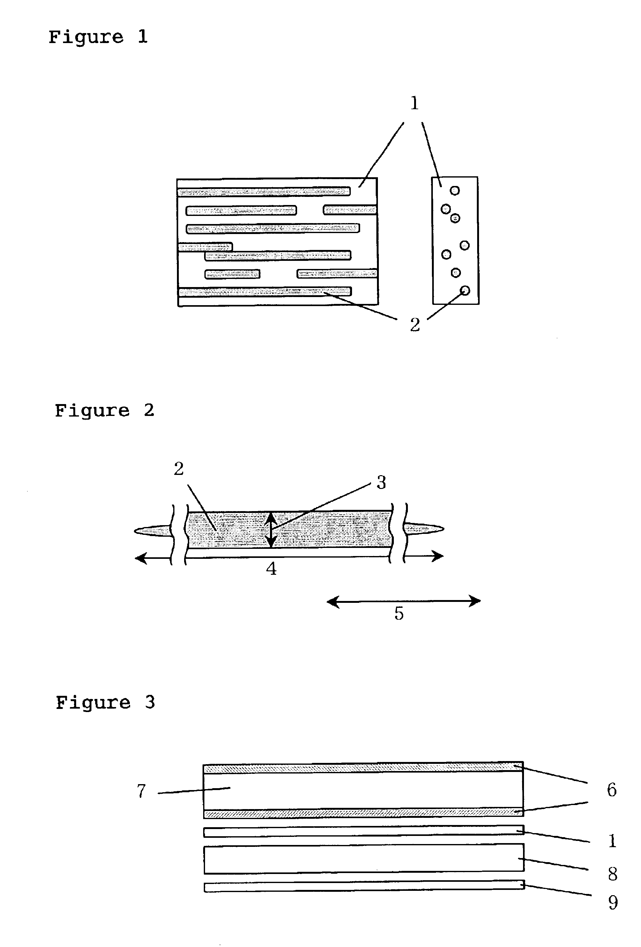
[0112]The composition fiber of the above LCP and the alicyclic polyolefin resin was embedded in an epoxy resin, and a sliced piece of about 90 nm was prepared by a cryo-microtome (−100° C.). After carrying out C deposition of the sliced piece, SEM observation was performed using Hitachi FE-SEM S900, and it was confirmed that LCP was made into rod-like dispersed phase and orientated along with fiber axis. The diameter of the dispersed phase was about several 10 nm. and the length was several μm.
(Scattering Anisotropy Evaluation)
[0113]Total light transmittance of the above film was measured. The transmittance in a transmission state was 90.7%. The transmittance in a scattering state was 27.1%. The difference was 63.6%. A high pol...
example 3
[0115]A film was produced as the same manner with Example 1, except that: polymethylmethacrylate (Sumipex EXN, produced by Sumitomo Chemical Co., Ltd., Tg 93° C., hereinafter may be referred to as PMMA) was used as the matrix phase resin material; a liquid crystal polymer (Rodran LC3000 produced by UNITIKA Ltd., FT 183° C., hereinafter may be referred to as Rodran) was used as the dispersed-phase resin material; the melt-kneading was carried out with setting a kneading temperature to 250° C.; the melt-spinning was carried out with setting the spinning temperature to 270° C.; and the film-formation was carried out with setting the press temperature to 160° C.
(Micro-Structure Observation)
[0116]The composition fiber of the above LCP and PMMA was embedded in an epoxy resin, and a sliced piece of about 90 nm was prepared by a cryo-microtome (−100° C.). After carrying out C-deposition of the sliced piece, SEM observation was performed using Hitachi FE-SEM S900. and it was confirmed that L...
PUM
| Property | Measurement | Unit |
|---|---|---|
| Temperature | aaaaa | aaaaa |
| Temperature | aaaaa | aaaaa |
| Length | aaaaa | aaaaa |
Abstract
Description
Claims
Application Information