Coated component with through-hole having improved surface finish

Inactive Publication Date: 2005-06-21
GENERAL ELECTRIC CO
View PDF4 Cites 22 Cited by
  • Summary
  • Abstract
  • Description
  • Claims
  • Application Information

AI Technical Summary

Benefits of technology

[0010]According to the present invention, there is provided a process of removing deposits from a through-hole in a component, an example being portions of a metallic and/or ceramic coating material deposited on a surface of an air-cooled gas turbine engine component. The process is particularly effective in removing a TBC material deposited in a cooling hole of a component as a result of coating a surface of the component with the TBC material, in which the

Problems solved by technology

In particular, the surface conditions of these surfaces have the appearance of bein

Method used


Image

  • Coated component with through-hole having improved surface finish
  • Coated component with through-hole having improved surface finish
  • Coated component with through-hole having improved surface finish

Examples


Example

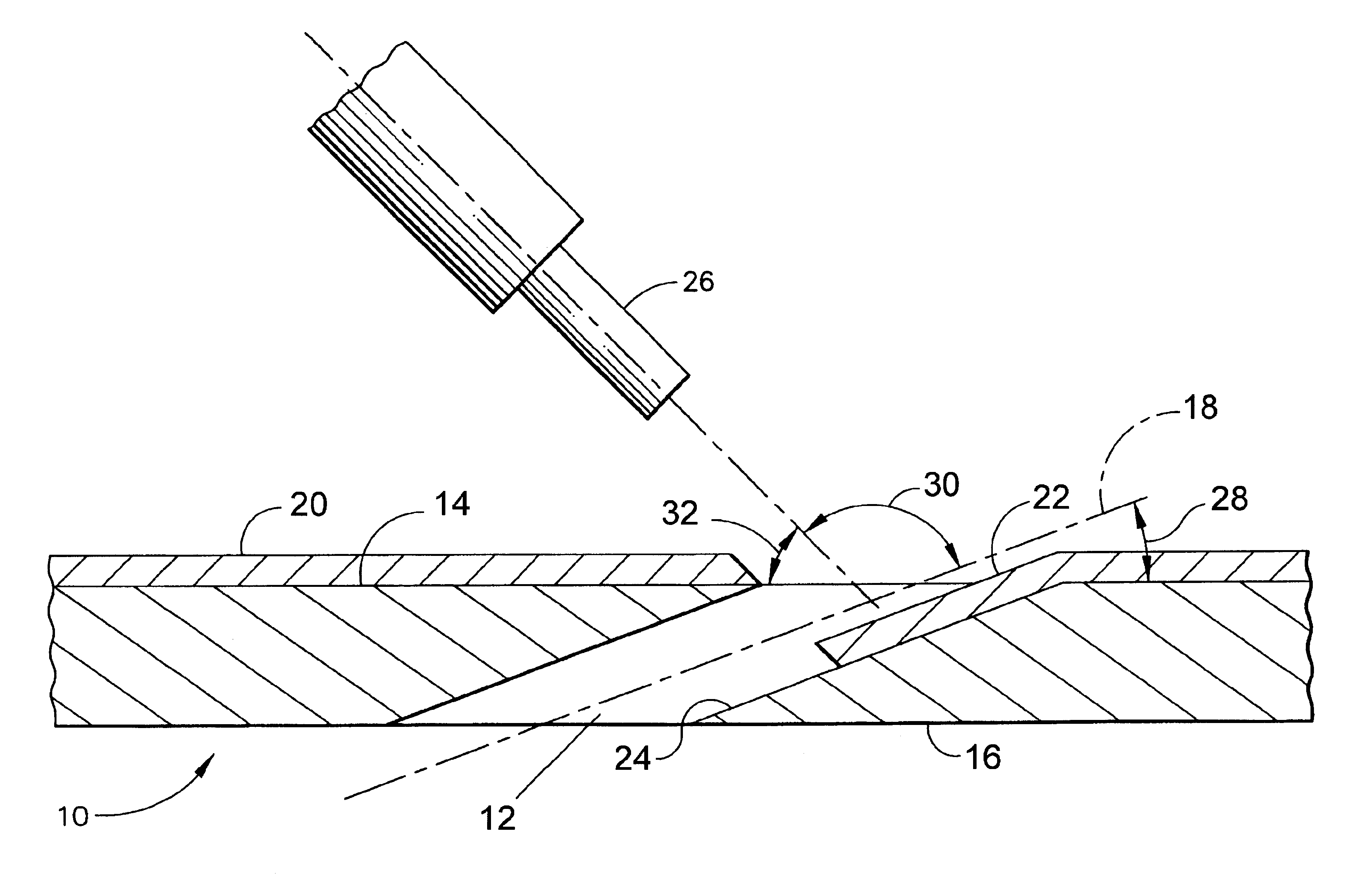
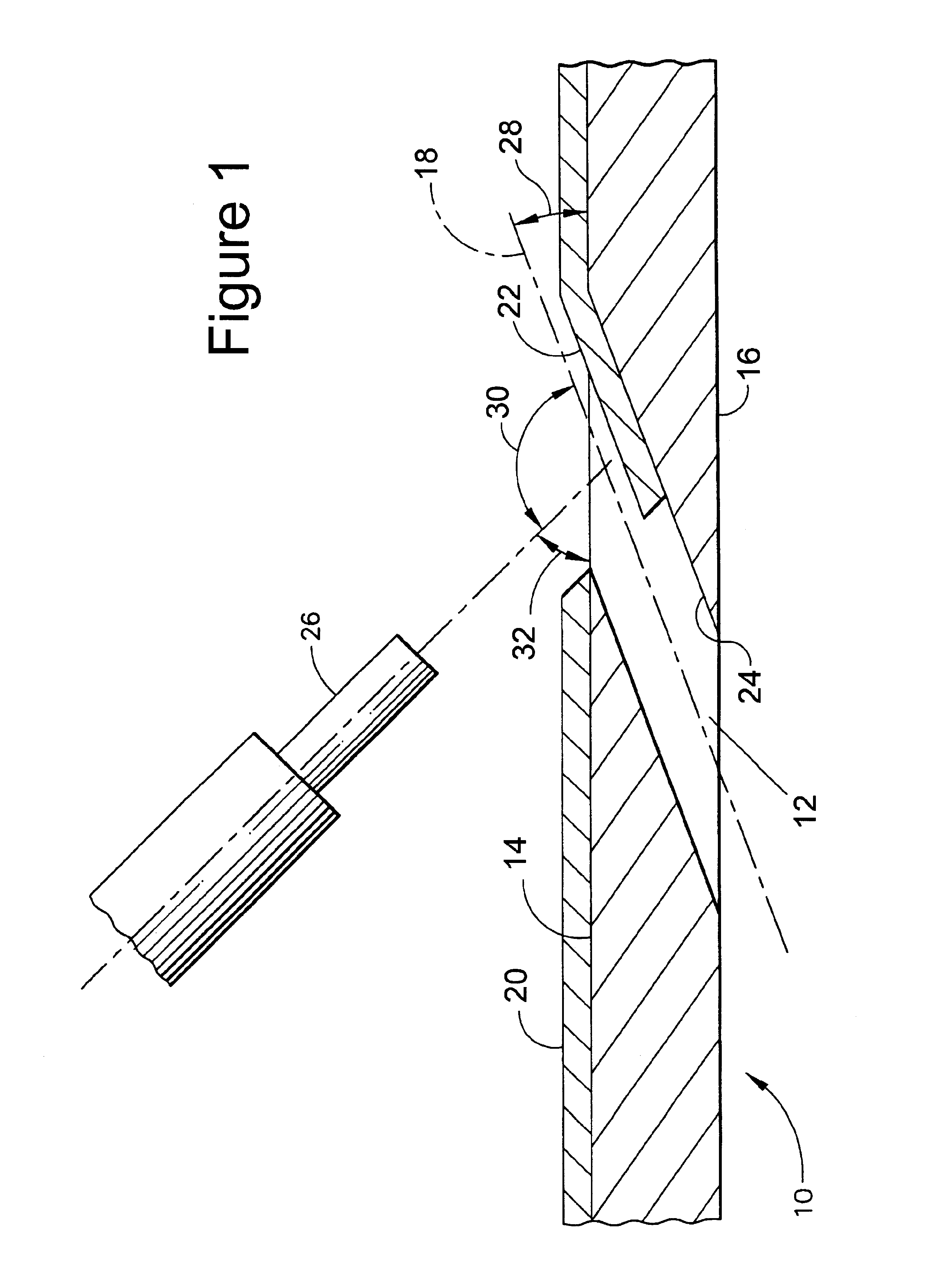
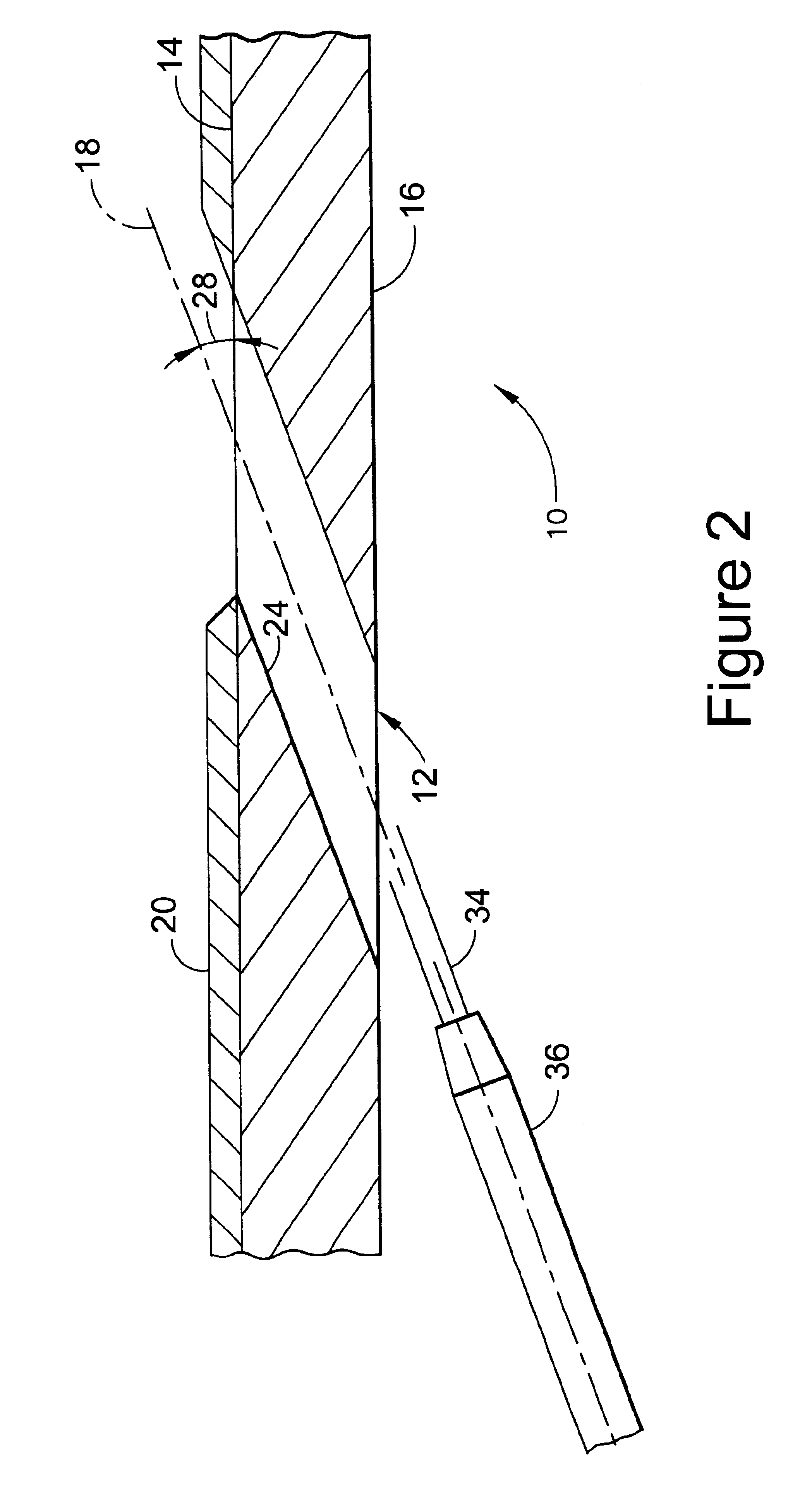
[0019]FIGS. 1 and 2 represent cross-sectional views through a cooling hole 12 that intersects two opposing surfaces 14 and 16 of an air-cooled combustor liner 10 of a gas turbine engine. The liner 10 may be formed of an iron, nickel or cobalt-base superalloy, though other high temperature materials could foreseeably be used. As known in the art, to minimize the service temperature of the liner 10, heat is transferred from the liner 10 by forcing bleed air through the cooling hole 12 from a passage defined in part by the surface 16. In addition, the amount of heat transferred to the surface 14 of the liner 10 can be reduced by forming the cooling hole 12 to be disposed at an acute angle 28 relative to the surface 14 of the liner 10, so that air discharged from the cooling hole 12 flows over the surface 14 of the liner 12. Suitable techniques for forming the hole 12 include EDM or laser drilling, though it is foreseeable that the hole 12 could be formed by such other methods as castin...


PUM

PropertyMeasurementUnit
Fractionaaaaaaaaaa
Lengthaaaaaaaaaa
Lengthaaaaaaaaaa

Abstract

A process of removing deposits from through-holes in a component, such as metallic bond coat and ceramic materials from cooling holes in an air-cooled gas turbine engine. The process is particularly effective in removing a TBC material deposited in a cooling hole of a component as a result of depositing a coating of the TBC material on a surface of the component, in which the deposit is removed from the cooling hole without damaging the cooling hole or the TBC coating surrounding the cooling hole on the coated surface of the component. A preferred feature is that the cooling hole, including the entrance to the hole at a surface of the component opposite the coated surface and the coating surrounding the exit of the hole at the coated surface, exhibits improved surface characteristics that increase the discharge coefficient of the cooling hole, as evidenced by an increase in the effective area of the cooling hole.

Description

CROSS REFERENCE TO RELATED APPLICATIONS[0001]This is a divisional application of U.S. patent application Ser. No. 10 / 086,266 , filed Mar. 1, 2002 now U.S. Pat. No. 6,663,919.BACKGROUND OF INVENTION[0002]1. Field of the Invention[0003]The present invention generally relates to coatings deposited on components with through-holes that are desired to remain open after the coating process. More particularly, this invention is directed to a method for removing coating deposits from through-holes in a component surface without damaging the hole walls and component surface, and to a gas turbine engine component equipped with cooling holes whose cooling effectiveness is promoted as a result of the removal process.[0004]2. Description of the Related Art[0005]Components located in certain sections of gas turbine engines, such as the turbine, combustor and augmentor, are often thermally insulated with a ceramic layer in order to reduce their service temperatures, which allows the engine to oper...

Claims


Application Information

Patent Timeline
IPC IPC(8): B23P6/00C23C4/00F01D5/18F01D5/28B24C11/00B24C1/00
CPCB23P6/002C23C4/00F01D5/186F01D5/288B23P2700/06Y10T29/49339F05D2230/13Y10T428/12361Y10T29/49318Y10T428/24273F05D2260/607Y10T428/249953
Inventor FARMER, GILBERTFEHRENBACH, JEFFREY ARNOLD
Owner GENERAL ELECTRIC CO
Why Eureka
Try Eureka