Position sensor to compensate for change of temperature coefficient of impedance of a detection coil

a technology of temperature coefficient and detection coil, which is applied in the field of position sensors, can solve the problems of increasing the number of parts difficulty in positioning parts relative to other parts, and complicated circuit configuration of the position sensor, so as to simplify the circuit configuration and reduce the dependence of the temperature coefficient of the detection coil on the displacement of the cor

Inactive Publication Date: 2005-06-21
MATSUSHITA ELECTRIC WORKS LTD
View PDF7 Cites 21 Cited by
  • Summary
  • Abstract
  • Description
  • Claims
  • Application Information

AI Technical Summary

Benefits of technology

[0015]According to the above arrangement, the detection coil is optimally selected depending on the object for position detection. Further, dependency of temperature coefficient of impedance of the detection coil on displacement of the cor

Problems solved by technology

As a result, it is necessary to compensate for an output voltage of the detection coil 302 in terms of circuit, configuration considering the temperature change, which makes the circuit configuration of the position sensor complicated.
Specifically, the above prior art proposes a technique of lessening dependency of the temperature coefficient of impedance Z of the detection coil 402 on the displacement X of the core 401 by providing the arrangement of the detection coil 402 and peripheral devices thereof in an attempt to solve the problem that the temperature coefficient of impedance Z depends on the displacement X. However, even in the above arrangement, there have occurred various problems such as increase of the number of parts constituting the position sensor, difficulty in positioning of parts relative to other parts, constraint in designing the detection coil, limited use of a sensor, and rising of cost in producing the sensor due to these reasons.
However, the linearity is lost at the opposite ends of the stroke.
However, desired linearity may not be obtainable for th

Method used


Image

  • Position sensor to compensate for change of temperature coefficient of impedance of a detection coil
  • Position sensor to compensate for change of temperature coefficient of impedance of a detection coil
  • Position sensor to compensate for change of temperature coefficient of impedance of a detection coil

Examples


first embodiment

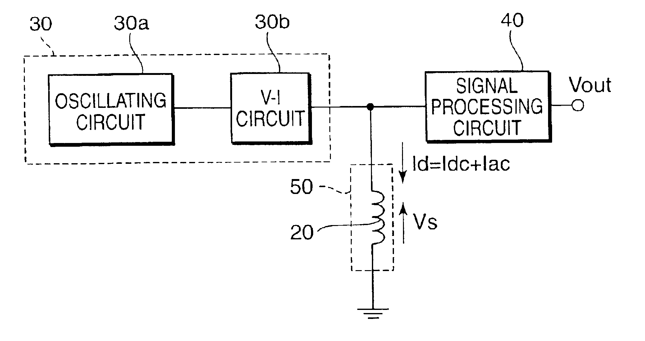
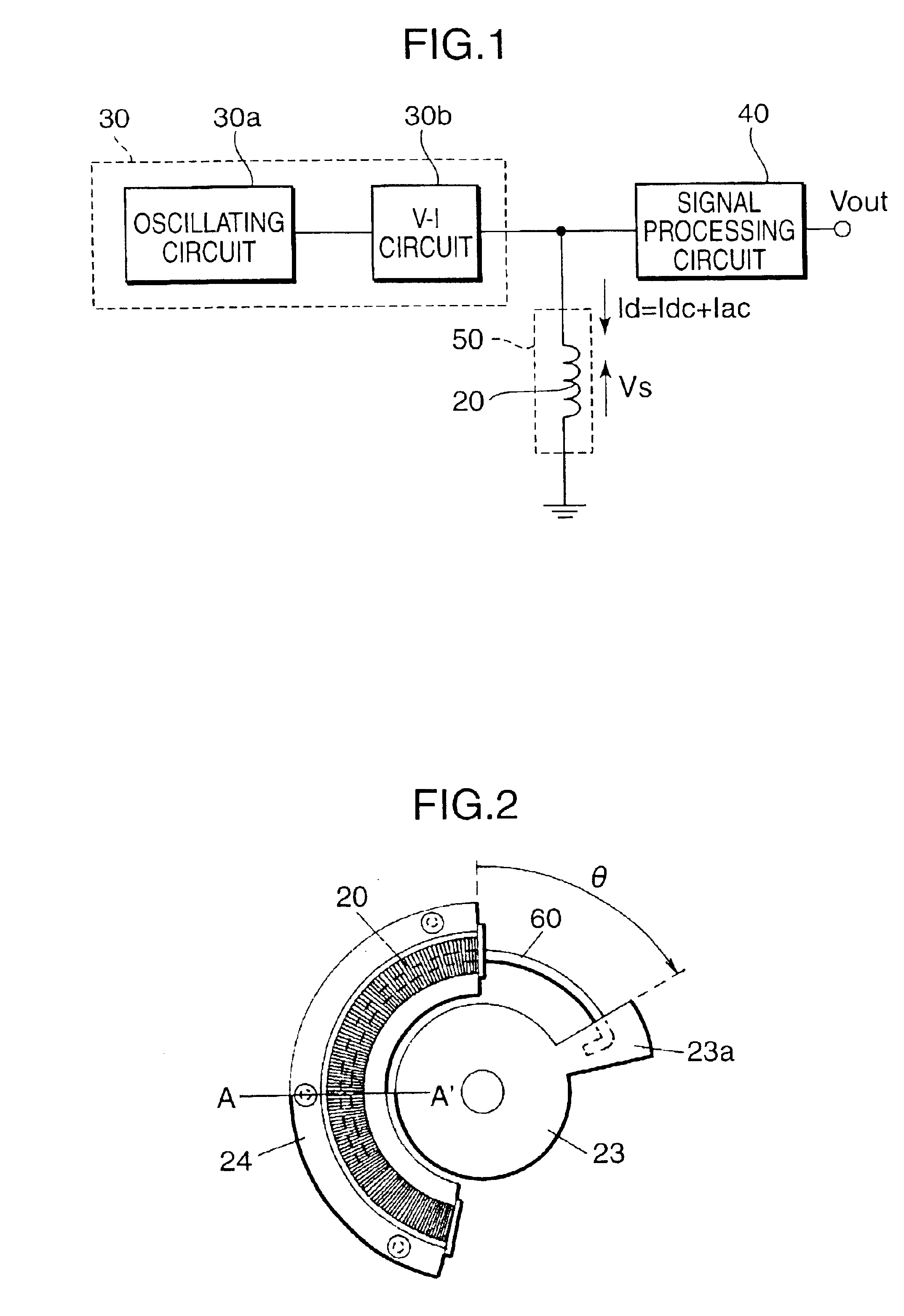
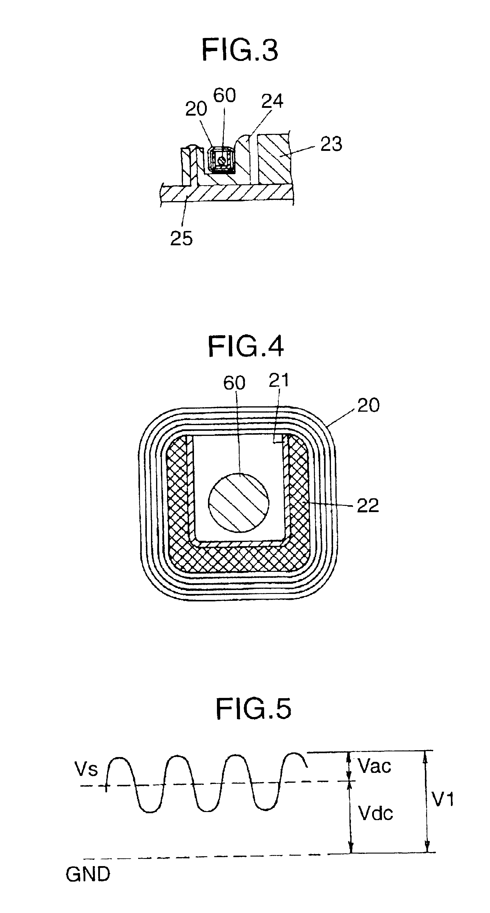
[0056]FIG. 1 is a diagram showing a circuit configuration of a position sensor in accordance with the first embodiment of this invention. FIG. 2 is a top plan view of the position sensor. FIG. 3 is a sectional view taken along the line A-A′ in FIG. 2. FIG. 4 is a sectional view of a detection coil 20.

[0057]The position sensor in accordance with the first embodiment has a generally U-shape in section, and comprises the detection coil 20, a movable block 23, a core 60, a curvature corrector 24, a housing 25, a constant current circuit 30, and a signal processing circuit 40. The detection coil 20 is produced by winding a wire around a curved bobbin 22 which has a given curvature. The curved bobbin 22 has a generally U-shape in section and is applied with a coating 21 on the inner surface of the U-shaped portion thereof. The movable block 23 is a cylindrical body having an axis of rotation coaxial with the center of the curved detection coil 20 with a protrusion 23a formed at an outer p...

second embodiment

[0095]In this embodiment, described is a temperature compensation method for keeping the temperature characteristic of impedance Z of the detection coil 20 from being affected by relative displacement of the core 60 to the coil 20 by setting a state where the value of Δ(dZac / dT) is minimized as an ideal state. The arrangement of the position sensor in this embodiment is substantially the same as that in the first embodiment. Accordingly, elements in the second embodiment which are identical to those in the first embodiment will be denoted at the same reference numerals, and description on the identical parts will be avoided.

[0096]As a first temperature compensation method, described is a method for matching the temperature change ratio of impedance Z of the detection coil 20 in the case where the core 60 is not passed through the detection coil 20 with the temperature change ratio thereof in the case where the core 60 is passed through the detection coil 20.

[0097]Impedance Z of the ...

third embodiment

[0111]In this embodiment, a method of improving linearity of output is described. The construction of the position sensor in accordance with the third embodiment is substantially the same as that in the first and second embodiments. Accordingly, elements in the third embodiment which are identical to those in the first and second embodiments will be denoted at the same reference numerals, and description on the identical parts will be avoided.

[0112]A first linearity improving method is to select an appropriate material for the core 60 and to set the frequency f of the alternate current Iac appropriately. The inventors of this invention carried out experiments concerning linearity of AC impedance Zac by changing the material of the core in relation to the detection coil 20 which has been exemplified in the first embodiment. FIG. 19 shows a list of the used metallic materials: soft magnetic iron, permalloy, electromagnetic stainless, SUS430, and iron chrome, and corresponding estimate...


PUM


Abstract

A direct current and an alternate current are simultaneously supplied from a constant current circuit to a detection coil. At least one of the ratio of the direct current to the alternate current, the ratio of an alternate current component to a direct current component of an impedance in a detecting section, a temperature characteristic of the ratio of the direct current to the alternate current, and a temperature characteristic of the ratio of the alternate current component to the direct current component of the impedance of the detecting section is set in such a manner that the margin of fluctuation of a temperature coefficient of a peak value of an output voltage from the detecting section in a whole displacement zone of a core relative to the detection coil is smaller than the margin of fluctuation of a temperature coefficient of the alternate current component of the impedance of the detection coil at the frequency of the alternate current.

Description

TECHNICAL FIELD[0001]This invention relates to a position sensor for detecting displacement of a movable object.BACKGROUND ART[0002]Heretofore, there has been proposed a position sensor constructed in such a manner that a core is passed through a detection coil to detect change of impedance of the detection coil and to output a signal indicative of displacement of the core relative to the detection coil. FIG. 34 is a diagram schematically illustrating a detecting section of such a conventional position sensor. FIG. 35 is a graph showing a relation between displacement X of a core and alternate current impedance or AC impedance Zac of a detection coil 2 (sic). FIG. 36 is a diagram showing an entire configuration of the circuit of the position sensor. The AC impedance Zac has a component of a real number and a component of an imaginary number. In FIG. 35, the greater the displacement X is, the more the passing amount of the core 301 through the detection coil 302 is with the result th...

Claims


Application Information

Patent Timeline
IPC IPC(8): G01D5/22G01D3/036G01D5/12G01D5/20G01D3/028
CPCG01D3/036G01D5/2208G01D5/2006G01D5/20
Inventor NIWA, MASAHISA
Owner MATSUSHITA ELECTRIC WORKS LTD
Why Eureka
Try Eureka