
Aberration correcting optical unit, optical pickup apparatus and information recording/reproducing apparatus with single and multi-layer electrodes

a technology of optical pickup and correction optical unit, which is applied in the direction of optical beam source, record information storage, instruments, etc., can solve the problems of large aberration of light beam, large influence of spherical aberration, and difficulty in improving the accuracy of information recording and information reproduction, etc., to achieve accurate reproduction, accurate reproduction, accurate reproduction

Inactive Publication Date: 2005-06-21
PIONEER CORP
View PDF15 Cites 13 Cited by
  • Summary
  • Abstract
  • Description
  • Claims
  • Application Information

AI Technical Summary

Benefits of technology

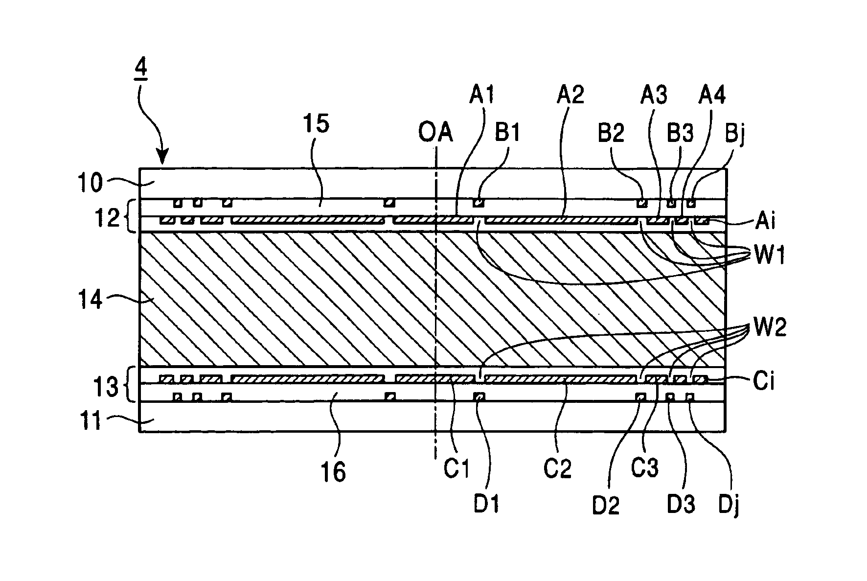
The present invention provides an aberration correcting optical unit that can accurately correct the influence of aberration in an information recording medium, such as a CD or a DVD. The optical unit includes an optical element and electrodes that apply voltage to the optical element to cause a phase change. The electrodes are arranged in a multi-layer structure to produce an electro-optical effect opposite to the aberration characteristics of the information recording medium. The optical unit can be used in an optical pickup apparatus or an information recording / reproducing apparatus to accurately reproduce information on the recording medium. The invention also provides an improved method for correcting aberration in an information recording medium using a liquid crystal element.

Problems solved by technology

An increased numerical aperture of an objective lens and the use of a short wavelength light beam, however, result in larger aberration of the light beam by the optical disc, causing difficulties in improving the accuracy of information recording and information reproduction.
This causes a problem of a larger influence of spherical aberration resulting from the birefringence.
Also, when a light beam of a short wavelength is used with an increased numerical aperture NA of an objective lens, influence of coma aberration cannot be negligible if the optical disc is inclined during recording or reproducing information so as to incline an incident angle (tilt angle) of the light beam with respect to the normal direction of the optical disc.
Further, the influence of aberration such as the above-described spherical aberration and coma aberration differs depending on the type of a particular optical disc since different types of optical discs such as CD and DVD have different structures and recording densities, thereby making it difficult to develop compatible optical pickup apparatus and information recording / reproducing apparatus.
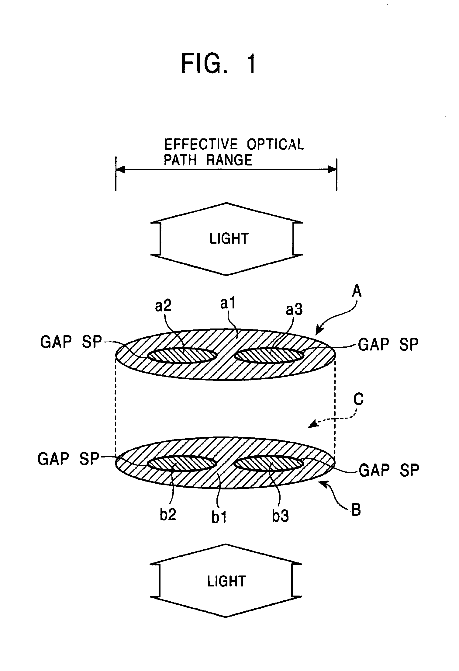
Therefore, no voltage is applied to the gaps SP, so that the foregoing structure suffers from an inability of controlling the alignment states in the liquid crystal element C corresponding to the gaps SP.
Also, when the transparent electrodes are divided by a larger number with the intention of making a finer correction for the influence of aberration, a large number of transparent electrodes are formed with required electrical insulating features therebetween within a limited effective optical path range in which the laser light or reflected light passes, resulting in an increased number of the gaps SP and a larger area occupied thereby.
As a result, a fine aberration correction becomes difficult.
Further, different voltages applied to mutually adjoining transparent electrodes result in abrupt discontinuous alignment states produced in the liquid crystal element C corresponding to the gaps SP intervening between the transparent electrodes.

Method used


Image

  • Aberration correcting optical unit, optical pickup apparatus and information recording/reproducing apparatus with single and multi-layer electrodes
  • Aberration correcting optical unit, optical pickup apparatus and information recording/reproducing apparatus with single and multi-layer electrodes
  • Aberration correcting optical unit, optical pickup apparatus and information recording/reproducing apparatus with single and multi-layer electrodes

Examples


Embodiment Construction

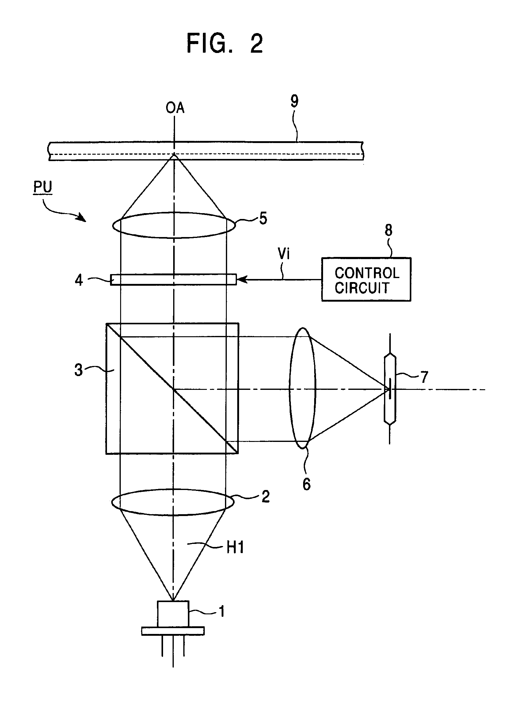
[0057]Embodiments of the present invention will hereinafter be described with reference to the accompanying drawings. FIG. 2 is a diagram illustrating the configuration of an optical pickup apparatus provided in an information recording / reproducing apparatus.

[0058]In FIG. 2, the optical pickup apparatus PU includes a light source 1 for emitting laser light H1, a polarizing beam splitter 3, an aberration correcting optical unit 4, an objective lens 5, a converging lens 6 and a photodetector 7. The components 1-7 are arranged along an optical axis OA. A control circuit 8 is provided in the optical pickup apparatus PU or in an information recording / reproducing apparatus for controlling the aberration correcting optical unit 4.

[0059]The aberration correcting optical unit 4 has an electro-optic element which exhibits an electro-optic effect that varies depending on an electric field applied thereto. More specifically, the aberration correcting optical unit 4 has a liquid crystal optical ...


PUM

PropertyMeasurementUnit
widthaaaaaaaaaa
thicknessaaaaaaaaaa
thicknessaaaaaaaaaa

Abstract

An aberration correcting optical unit includes an optical element for causing a phase change to light passing therethrough by the application of voltage and electrode layers for applying voltages to the optical element. The optical element is sandwiched between the electrode layers. At least one of the electrode layers includes a plurality of electrodes which are electrically isolated from one another. The plurality of electrodes are disposed such that an electric field generated in a portion of the optical element corresponding to a portion between the plurality of electrodes is larger than a predetermined intensity when a predetermined voltage is applied to the optical element.

Description

BACKGROUND OF THE INVENTION[0001]1. Field of the Invention[0002]The present invention relates to an aberration correcting optical unit for correcting aberration when information is recorded on or reproduced from an information recording medium such as an optical disc as well as an optical pickup apparatus having the aberration correcting optical unit and an information recording and / or reproducing apparatus (hereinafter, referred to as “an information recording / reproducing apparatus”).[0003]2. Description of the Related Art[0004]Optical discs such as a CD (Compact Disc) and a DVD (Digital Video Disc or Digital Versatile Disc) are known as information recording media for optical information recording or reproduction. In addition, a variety of different optical discs are now under development, such as an optical disc specialized for reproduction, a write-once optical disc capable of additionally recording information thereon, a rewritable optical disc capable of erasing information th...

Claims


Application Information

Patent Timeline
Patent Type & Authority Patents(United States)
IPC IPC(8): G02B27/00G02F1/13G02F1/1343G11B7/125G11B7/135
CPCG02B27/0068G02F1/134309G11B7/13925G11B7/1369G02F2203/18
Inventor IWASAKI, MASAYUKIOGASAWARA, MASAKAZU
Owner PIONEER CORP
Learn More