
Spatio-temporal filter and method

a spatial-temporal filter and filtering technology, applied in the field ofsignal and image processing systems, can solve the problems of large computational rates, slow response time, and prohibitive net power dissipation of large staring arrays, and achieve the effect of eliminating complex polymer device processing

Inactive Publication Date: 2005-06-21
COMPUTATIONAL SENSOR
View PDF5 Cites 19 Cited by
  • Summary
  • Abstract
  • Description
  • Claims
  • Application Information

AI Technical Summary

Benefits of technology

[0019]The above objectives of the present invention are realized by providing a method and apparatus for spatial frequency filtering employing switched capacitor resistive interconnects between processing nodes of analog VLSI circuits that allow flexible control of blurring for spatial frequency filtering. The combination of a switched capacitor resistive layer and a charge blurring structure involving the controlled diffusion from a separate capacitor array, charged in proportion to the incoming image intensity, performs the blurring operation in a flexible and anisotropically constrainable manner enabling a variety of image convolution operations.
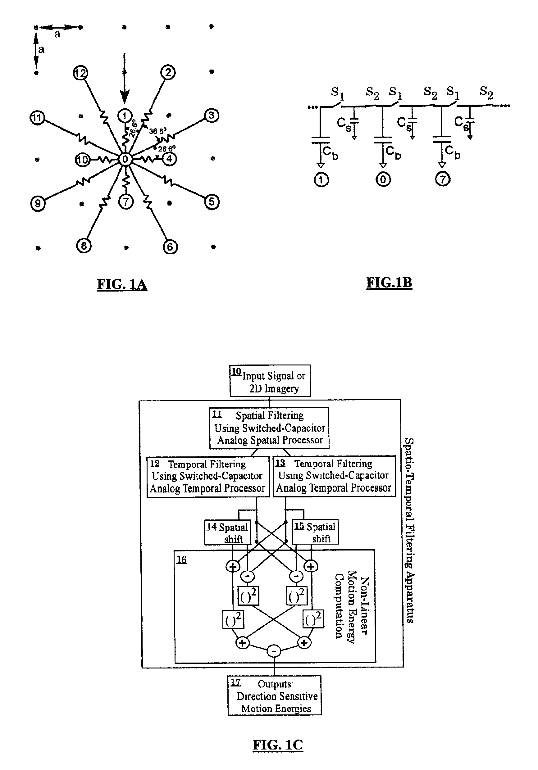
[0020]With reference to FIGS. 1A and 1B, a resistive network interconnecting grid node 0, on a rectilinear grid with grid spacing a, to neighboring princicple axis nodes and grid nodes √{square root over (5)}a distant is shown in FIG. 1A. A switched capacitor implementation, FIG. 1B, is shown only for the connections between the three vertical nodes as indicated by the vertical arrow in FIG. 1A. A capacitor CS and an adjacent switch on each side (labeled 1 and 2), define a resistive path between two node capacitors CB with an effective resistance controlled by the rate at which the switches operate. This method enables the determination of subtle discrimination of non-stationary spatial frequency components and other filtering operations. The present approach further eliminates complicated polymer device processing subsequent to the Silicon VLSI foundry device fabrication.

Problems solved by technology

Image processing systems are important and, in some cases, critical, in applications where limited space, mass, and power requirements are present together with the need for very large computational rates.
This approach is limited to relatively large unit cell areas and although the FET operation in subthreshold conditions resulted in reduced power consumption as compared to conventional designs, the net power dissipation for a large staring array is prohibitive.
Furthermore, this approach suffers from slow response time that is incompatible with the readout requirements of contemporary high frame rate staring array readout focal plane technology.
This has been accomplished by the use of capacitor storage to inject charge discretely into the resistive grid array resulting in a Gaussian blurring.
However the complexities and control of post foundry processing of the polymer resistive layer makes that process unstable and disadvantageous for production application.
However, in practice this approach requires a separate anisotropic application for each anisotropic filtering direction and degree of anisotropy.
This results in a large number of chips to accomplish the same filtering operation as well as the insertion loss associated with each additional chip.
Although these systems are extremely versatile, they are not able to process large images at high rates because the digital processors employed in these systems have limited computational power and require a large amount of electrical power to operate (a typical desktop computer consumes about 75 watts).
When limited to using only low powered devices, the existing data processing systems cannot handle high data rates.
In other words, existing digital processing systems lack the ability to process large amounts of data in real time with limited power.
Currently available analog signal and image processing systems have little flexibility or programmability, and therefore device operation is highly restrictive with a limited range of applications.
The prior art discussed above does not adequately address these needs.

Method used


Image

  • Spatio-temporal filter and method
  • Spatio-temporal filter and method
  • Spatio-temporal filter and method

Examples


examples

Cruise Missile Detection:

[0100]For a cruise missile or aircraft moving with respect to an earth background and viewed by an imaging seeker on an interceptor, both the background and the cruise missile target will exhibit relative motion with respect to the interceptor. However, the earth background will have motion determined by the interceptor's trajectory and the target will have a relative motion (different than the background) determined by the relative velocity between the interceptor and the target. In addition, most of the resolved feature sizes of the background will not have the same spatial extent and / or 2D aspect ratio as the target. Thus, 2D spatial frequency filtering of a scene to extract only those features which are comparable in size and shape to the target, followed (or preceded) by temporal filtering of a series of scenes and extracting the features which have a prescribed relative motion through the motion-energy computation acting on the filtered data, provides ...


PUM


Abstract

A system, apparatus and methods are disclosed for the spatial and temporal processing of time dependant array data using analog signal processors. In one embodiment, a programmable array of switched capacitors is used to provide tunable parameters for controlling the desired processing of input data streams. The switched capacitor implementation of a spatial filter provides a massively parallel device that can be programmed to perform isotropic and spatially-oriented anisotropic filtering with low power demands. The system further includes the ability to combine differently filtered output streams with independent multiplicative weights. In another embodiment, the nonlinear spatio-temporal motion energy of a two-dimensional image stream data is computed. The spatial-temporal filter is able to combine multiple analog filters, both spatial and temporal, to perform complex spatial-temporal filtering operations implemented by Gaussian kernel filtering chips. It enables the use of analog spatial-temporal filtered data provided by the chip for computing scene motion energy.

Description

[0001]This application claims the benefit of Provisional Application No. 60 / 292,219, filed May 21, 2001.STATEMENT REGARDING FEDERALLY SPONSERED RESEARCH OR DEVELOPMENT[0002]This invention was made, in part, with Government support under contract DASG60-99-C-0017 awarded by U.S. Army Space and Missile Defense Command. The Government has certain rights in the invention.BACKGROUND OF THE INVENTION[0003]1. Field of the Invention[0004]The present invention relates to signal and image processing systems; more particularly, the present invention relates to the real-time spatial and temporal processing of time dependent array data. The present invention also relates to compact, low powered analog VLSI devices that are used in performing spatial and temporal data processing of signals and images.[0005]2. Prior Art[0006]Spatial and temporal filtering is essential to a variety of signal and image processing applications. Applications such as security and surveillance rely on the real-time spat...

Claims


Application Information

Patent Timeline
Patent Type & Authority Patents(United States)
IPC IPC(8): G06E3/00
CPCG06E3/005
Inventor LANGAN, JOHN D.SCOTT, JEFFREY S.STOBBE, PETER
Owner COMPUTATIONAL SENSOR
Learn More