In situ retreival of contaminants or other substances using a barrier system and leaching solutions and components, processes and methods relating thereto

a barrier system and in situ retreival technology, applied in nuclear engineering, radioactive decontamination, transportation and packaging, etc., can solve the problems of large volume of buried waste, long-standing confinement, management and disposal of various types of waste,

Inactive Publication Date: 2005-06-28
BATTELLE ENERGY ALLIANCE LLC
View PDF66 Cites 21 Cited by
  • Summary
  • Abstract
  • Description
  • Claims
  • Application Information

AI Technical Summary

Problems solved by technology

Containment, management, and disposal of various types of waste are long-standing problems.
Early waste management and disposal systems were primitive, as there were few or no disposal or environmental regulations in place at the time.
The volume of waste that has been buried is tremendous.
Further, much of the waste that was buried comprises heavy metals such as mercury and cadmium, carcinogenic materials such as trichloroethylene, radioactive materials, and other hazardous substances.
Because groundwater is a major source of water for drinking and for agriculture, contamination of the groundwater by leaching is a major concern.
At least some of the contaminated groundwater finds its way into waterways such as streams, rivers, and lakes, thus polluting those waterways and poisoning the plant and animal life.
Obviously, polluted waterways pose a threat to humans as well, particularly in the case of waterways and bodies of water used for recreational purposes and/or as a source of drinking water.
While many of the problems associated with buried waste concern the effect of leachate on groundwater, buried waste also typically emits gas phase contaminants that must likewise be contained and managed.
Such gas phase contaminants can also pollute the soil and the groundwater, and may build up to unsafe pressures which could ultimately result in explosion and/or atmospheric venting of the gas.
Such approaches are problematic for a variety of reasons.
In particular, many of these remediation techniques are expensive and potentially hazardous.
Further, it is difficult to verify the effectiveness of many of the treatments and remediation-type approaches may not be appropriate for all types of contaminated material.
Finally, determining the proper remediation technique is, in itself, a complex and time-consuming process, particularly in view of the web of regulations and procedures ...

Method used


Image

  • In situ retreival of contaminants or other substances using a barrier system and leaching solutions and components, processes and methods relating thereto
  • In situ retreival of contaminants or other substances using a barrier system and leaching solutions and components, processes and methods relating thereto
  • In situ retreival of contaminants or other substances using a barrier system and leaching solutions and components, processes and methods relating thereto

Examples


first embodiment

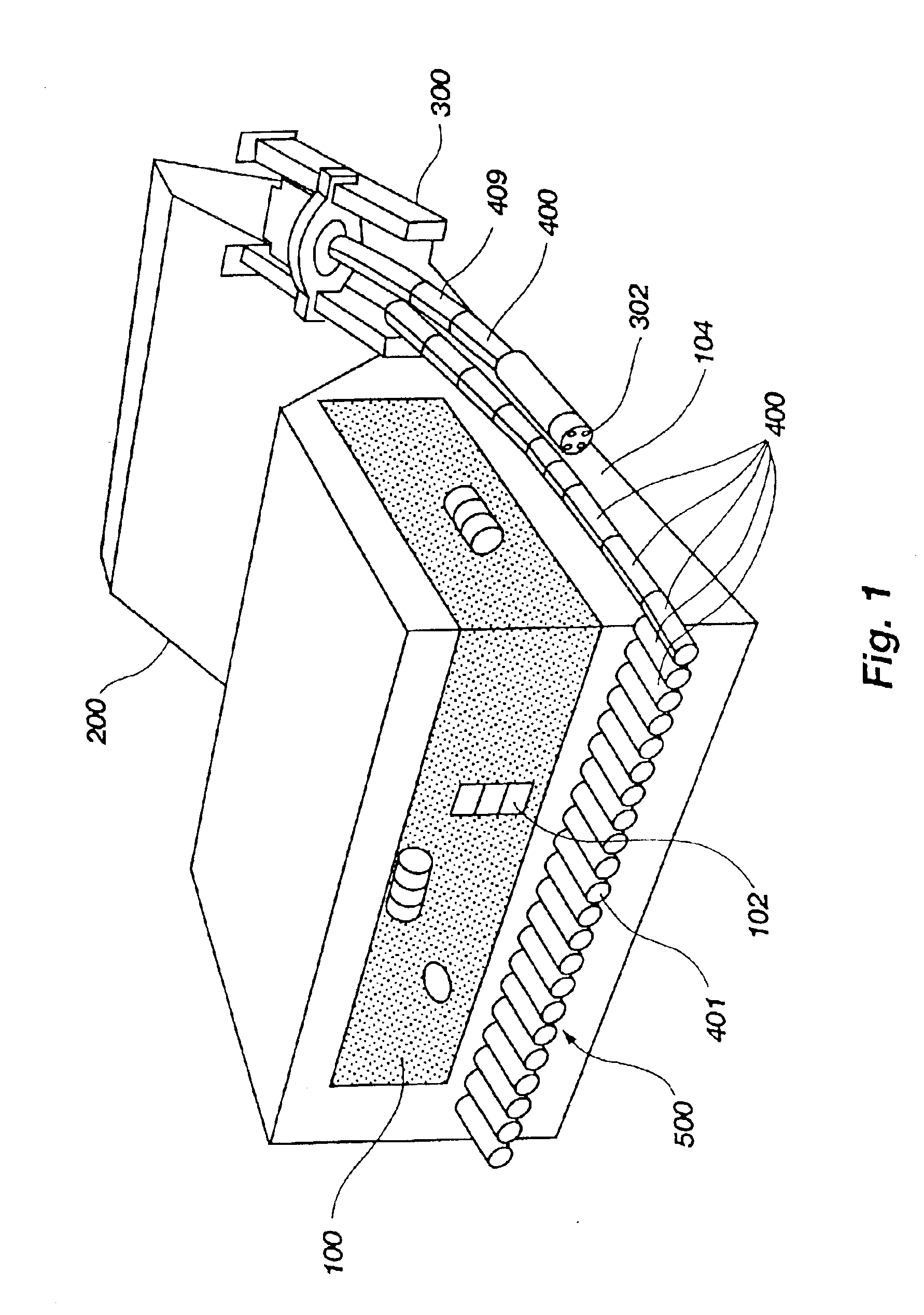
[0040]FIG. 1 depicts a zone of interest 100 to be isolated by a barrier 500 useful for practicing methods and processes in accordance with the principles of the present invention. In order to contain zone of interest 100, a trench 200 is first excavated on either side of zone of interest 100 (only one trench is shown) containing buried waste 102. Micro tunneling device 300 is then placed in trench 200. Trench 200 facilitates the placement of micro tunneling device 300, but the creation of trench 200 may be omitted in some embodiments. If trench 200 is excavated, the removed soil, if contaminated, may be disposed of by appropriate and approved methods. Additionally, any soil excavated by tunneling device 300 also be collected, scanned, and disposed of by similar methods.

[0041]One type of micro tunneling device 300 is known as a micro tunnel boring machine, or micro TBM. In a currently preferred embodiment, micro tunneling device 300 comprises an auger head 302 or the like for rotary ...

second embodiment

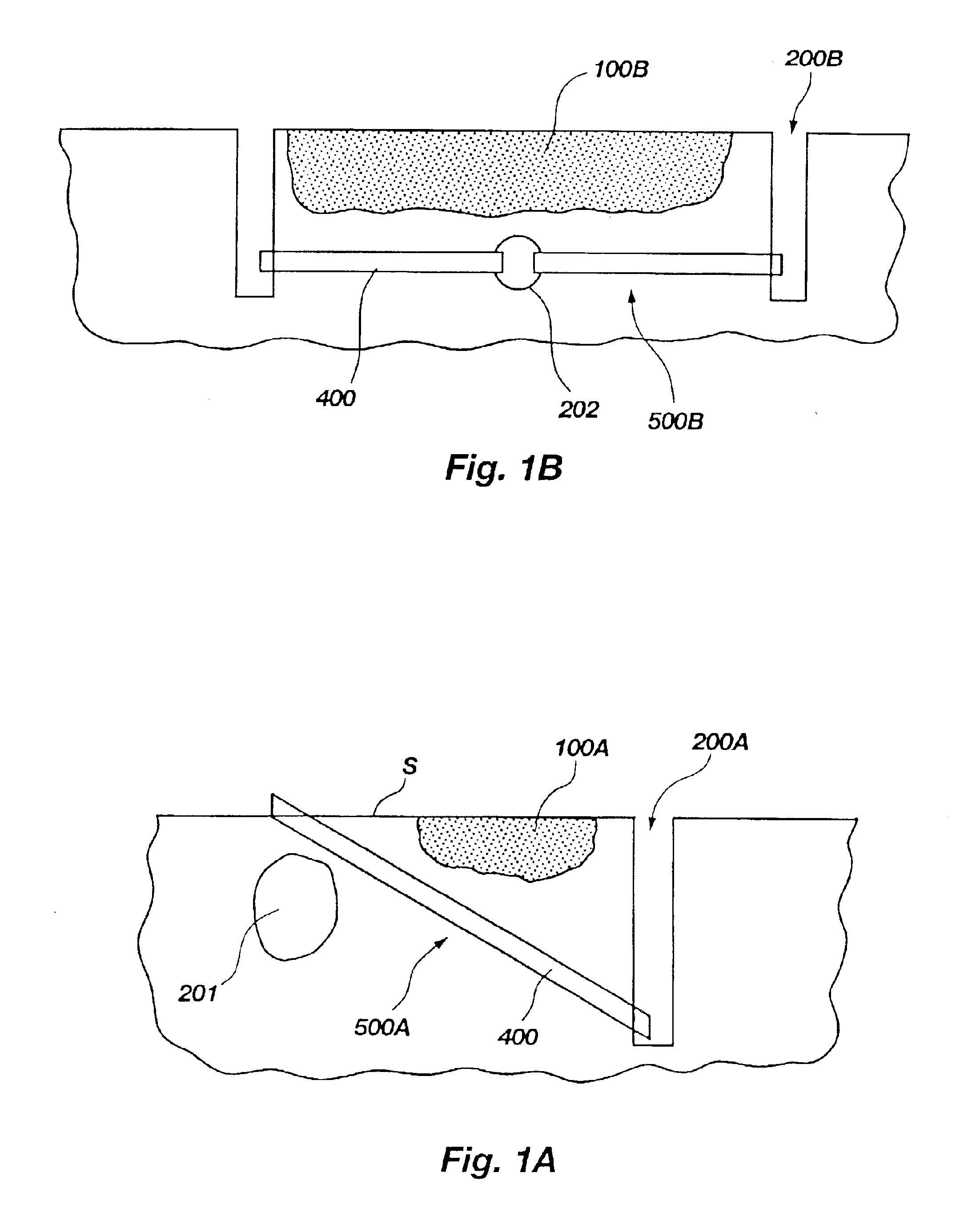
[0043]FIG. 1A illustrates a barrier 500A used to contain a zone of interest. In the FIG. 1A embodiment, a single trench 200A is excavated on one side of the zone of interest 100A. This may be done where desired, or where a subsurface object 201 prevents the placement of a second trench 200A. The barrier 500A is formed by boring laterally adjacent tunnels and lining with casing sections 400 as described previously herein, only the barrier is formed by running the casing sections 400 from the surface S to the single trench 200A.

[0044]FIG. 1B similarly illustrates yet another embodiment of a barrier 500B that may be used to contain a zone of interest 100B. A central tunnel 202 is bored beneath the zone of interest. Two trenches 200B are excavated on opposite sides of the zone of interest 100B substantially parallel to central tunnel 202 and casings 400B are placed in laterally adjacent tunnels bored from each of the trenches 200B to the central tunnel 202, forming barrier 500B. A singl...


PUM


Abstract

Processes and methods relating to treating contaminants and collecting desired substances from a zone of interest using subterranean collection and containment barriers. Tubular casings having interlock structures are used to create subterranean barriers for containing and treating buried waste and its effluents. The subterranean barrier includes an effluent collection system. Treatment solutions provided to the zone of interest pass therethrough and are collected by the barrier and treated or recovered, allowing on-site remediation. Barrier components may be used to in the treatment by collecting or removing contaminants or other materials from the zone of interest.

Description

RELATED APPLICATIONS[0001]This application is a continuation-in-part of U.S. application Ser. No. 10 / 062,817, filed Feb. 1, 2002 and entitled SUBSURFACE MATERIALS MANAGEMENT AND CONTAINMENT SYSTEM, COMPONENTS THEREOF AND METHODS RELATING THERETO, now U.S. Pat. No. 6,758,634 which is incorporated herein by reference in its entirety, which claims the benefit of U.S. Provisional Application No. 60 / 267,320, filed Feb. 6, 2001 entitled SUBSURFACE MATERIALS MANAGEMENT AND CONTAINMENT SYSTEM, which is incorporated herein by reference in its entirety and also is a continuation-in-part of U.S. application Ser. No. 09 / 729,435, filed Dec. 4, 2000, and entitled ADVANCED CONTAINMENT SYSTEM, now U.S. Pat. No. 6,575,663 which is incorporated by reference herein in its entirety.GOVERNMENT RIGHTS[0002]The United States Government has certain rights in this invention pursuant to Contract No. DE-AC07-99ID13727, and Contract No. DE-AC07-05ID14517 between the United States Department of Energy and Batte...

Claims


Application Information

Patent Timeline
IPC IPC(8): B09B1/00B09C1/00E02D19/18E02D31/00E02D19/00E02D5/08
CPCB09B1/00B09C1/002E02D31/006E02D19/185E02D5/08
Inventor NICKELSON, REVA A.WALSH, STEPHANIERICHARDSON, JOHN G.DICK, JOHN R.SLOAN, PAUL A.
Owner BATTELLE ENERGY ALLIANCE LLC
Why Eureka
Try Eureka