Water block removal with surfactant based hydrocarbonaceous liquid system

a hydrocarbonaceous liquid and surfactant technology, applied in the direction of sealing/packing, other chemical processes, borehole/well accessories, etc., can solve the problems of limited success of such approaches, less than completely successful, and less desirable

Inactive Publication Date: 2005-06-28
PHILLIPS 66 CO +1
View PDF16 Cites 97 Cited by
  • Summary
  • Abstract
  • Description
  • Claims
  • Application Information

AI Technical Summary

Benefits of technology

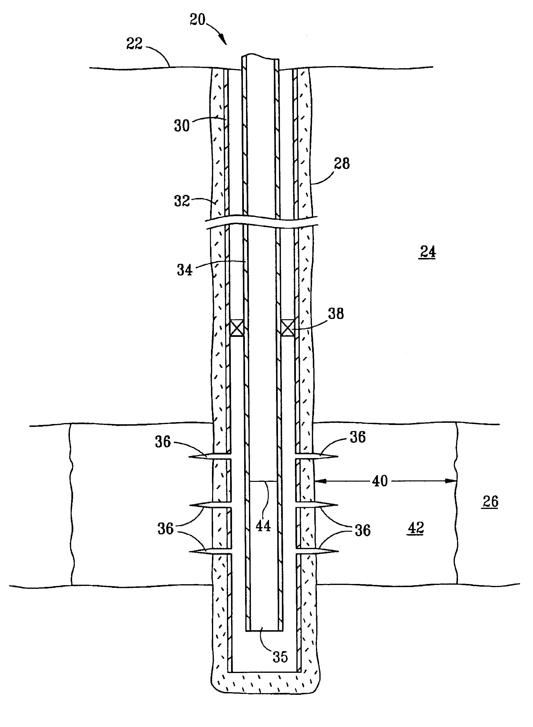
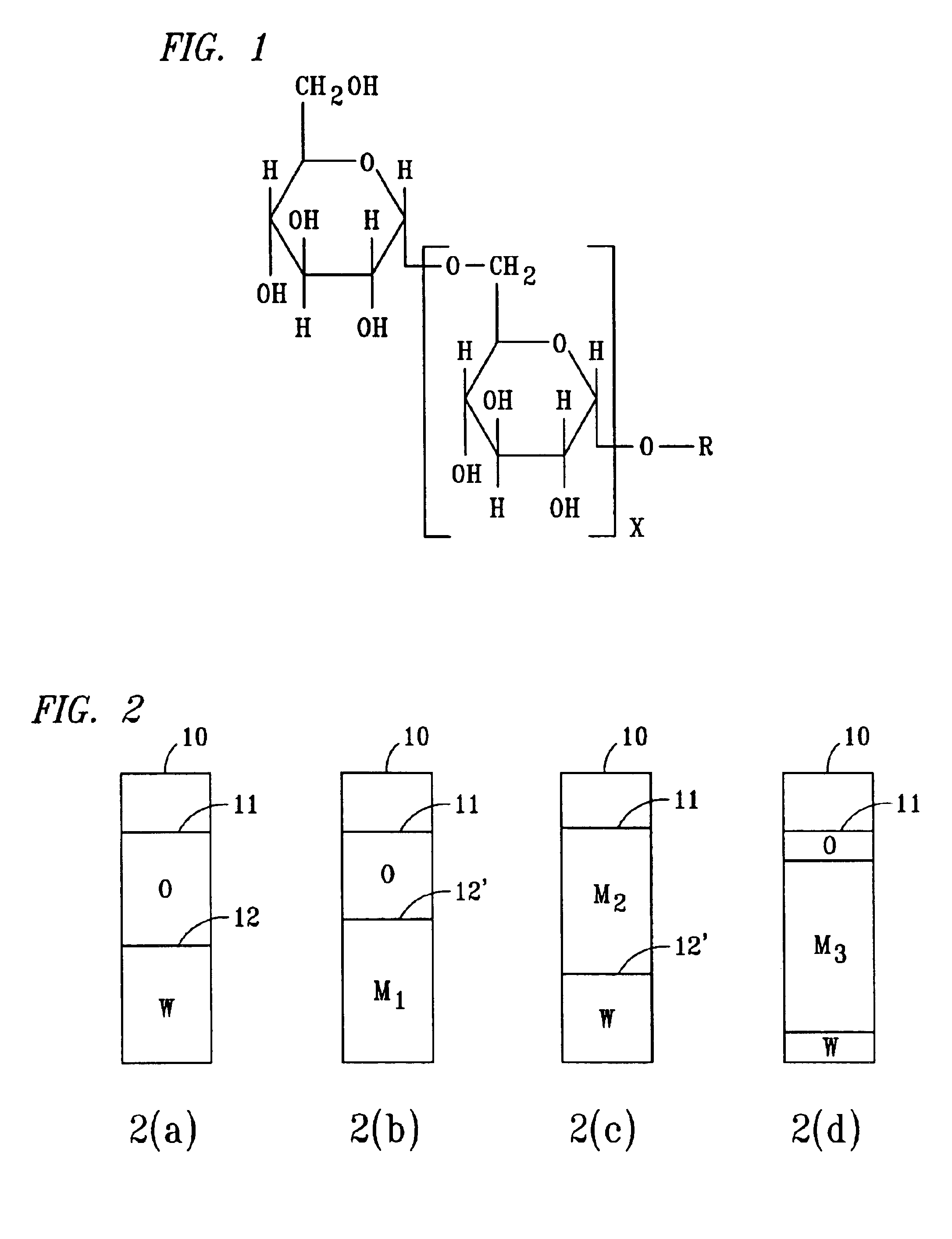
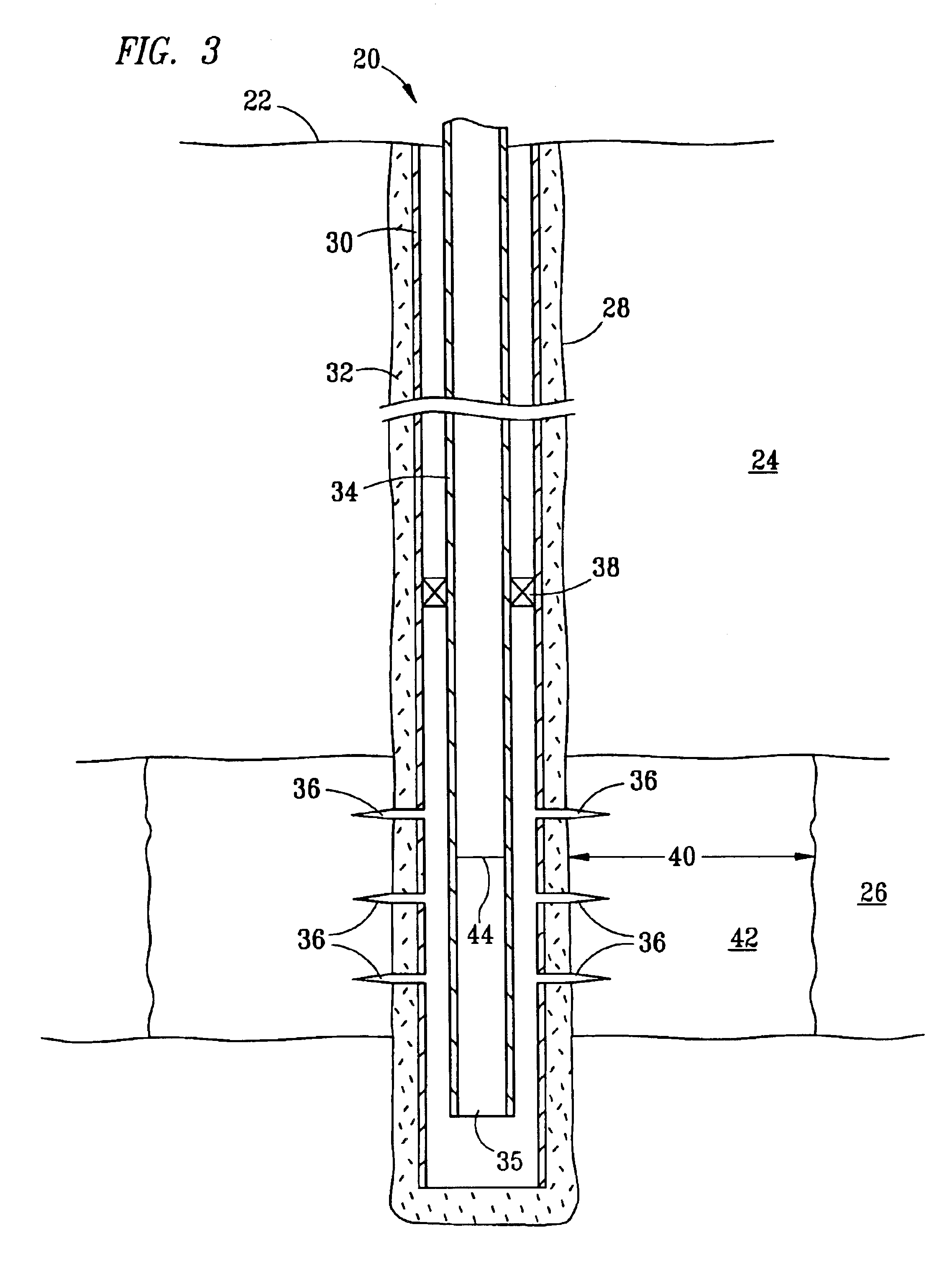
[0011]The present invention relates to a method for removing bound water from a near-wellbore portion of a subterranean formation containing crude oil and penetrated by a wellbore, the method comprising: injecting into the near-wellbore portion a quantity of a mixture containing a hydrocarbonaceous liquid, the hydrocarbonaceous liquid being miscible with the crude oil in the formation; about 0.5 to about 2 volume percent of an ethoxylated alcohol, the alcohol containing from about 8 to about 12 carbon chain length alkyl groups with an average of about 2 to about 4 ethylene oxide groups per molecule of alcohol; about 0.2 to about 2 volume percent of at least one alkylpolyglycoside containing alkyl groups containing from about 8 to about 16 carbon atoms and having an average oligomerization number from about 1.2 to about 1.8; and, about 1.5 to about 4 volume percent of a linear alkyl alcohol containing from about 4 to about 6 carbon atoms, the quantity being sufficient to fill the near-wellbore portion of the formation to a radial distance outwardly from the wellbore equal to from about 6 inches to about 3 feet; maintaining the mixture in the near-wellbore portion for a time from about 8 to about 96 hours; and, removing the mixture from the near-wellbore portion.

Problems solved by technology

The presence of water above the in-situ water saturation level can and does typically inhibit the production of crude oil from the formation.
The use of such approaches, while they may have been limitedly successful in some instances, are generally less than completely successful and are less desirable because of the safety concerns on the use of highly flammable methanol solvent.

Method used


Image

  • Water block removal with surfactant based hydrocarbonaceous liquid system
  • Water block removal with surfactant based hydrocarbonaceous liquid system
  • Water block removal with surfactant based hydrocarbonaceous liquid system

Examples


example 1

[0042]

TABLE IInterfacial Tension MeasurementArctic DieselSurfactant FluidEquilibrationComposition6% KCl BrineTemperatureIFT, dyne / cm80%20% 68° F.0.001837080%20%160° F.0.000268060%40% 68° F.0.019680060%40%160° F.0.0008835

[0043]Quantities of the Arctic diesel surfactant fluid composition as described above were mixed with KCl brine in the quantities shown. The quantities of brine in the test were chosen to reflect the range of water saturation present in the near wellbore formation. The KCl brine is used because the drill-in fluid composition, hence the drill-in-fluid filtrate, contains a brine salinity of 6 percent by weight KCl brine. The interfacial tension between the microemulsion phase and excess brine phase in the mixture is then measured by the spinning drop apparatus at the temperatures shown. It will be observed that these interfacial tensions are very low. By comparison, the interfacial tension between oil and water at room temperature is typically considered to be about 40...

example 2

[0044]In this Example, core plugs of a formation known to imbibe water were tested. These cores were virgin cores from a formation and were 1 inch in outer diameter by 1 to 2 inches long. In these tests, the core plugs were first treated by passing oil and then water through the cores. Thereafter the composition of the present invention was injected into the cores. The test program consisted of:

[0045]1. Drill plugs (1″ OD) from preserved core material using liquid nitrogen.

[0046]2. Mount test samples (plugs), apply full reservoir pressure and overburden pressure and heat to reservoir temperature.

[0047]3. Press aqueous filtrate from samples of a water-based drilling mud, specifically FLO-PRO drilling field mud (Trademark of M-I, LLC).

[0048]4. Measure baseline permeabilities to oil on the samples at 5, 20, 50, and 100 psi drawdown pressure levels.

[0049]5. At 100 psi overbalance level flush plug with the aqueous filtrate until approximately 2 pore volumes of production of filtrate is r...

example 3

[0058]An actual well having 2,300 feet of 6-⅛″ horizontal open-hole section in a producing formation in the North Slope of Alaska was treated with the composition of the present invention. The Arctic diesel oil was present in an amount of 96.5 volume percent, the alkylpolyglycoside was present in an amount of 0.42 volume percent with the ethoxylated alcohol and the linear alkyl alcohol being present in amounts of 1.05 volume percent and 2 volume percent respectively.

[0059]

Test III. Field TestFlowingOilGas / OilTubing PressureTemperatureDatebbl / dayRatio (GOR)(FTP) (psi)° F.Pre-treatment93694318852Post-treatmentDay 1100192179857Day 2262861221677Day 31843105619871Day 4168488219571Day 5132065918966Day 6173393619567Day 7174389219567

[0060]It is immediately apparent that the oil production from the treated well has been increased from 936 barrels per day (bbl / day) prior to treatment to about 1743 bbl / day after the treatment. This is a significant improvement, almost a doubling of the product...


PUM

PropertyMeasurementUnit
radial distanceaaaaaaaaaa
timeaaaaaaaaaa
volume percentaaaaaaaaaa

Abstract

A composition, formulation, and method for removing water from a near-wellbore portion of a subterranean formation containing a crude oil and penetrated by a wellbore. The formulation contains alkylpolyglycoside, ethoxylated alcohol and linear alkyl alcohols. The composition contains a hydrocarbonaceous liquid, alkylpolyglycoside, ethoxylated alcohol and linear alkyl alcohol.

Description

FIELD OF THE INVENTION[0001]This invention relates to a composition and method for removing water from the near-wellbore portion of a subterranean formation containing a crude oil and penetrated by a wellbore.BACKGROUND OF THE INVENTION[0002]In many instances, when wellbores are drilled to penetrate a subterranean oil-bearing formation, it is found that upon completion of the wellbores, whether using an oil-based drilling mud, water-based drilling mud or water-based drill-in-fluids, the near-wellbore portion of the formation frequently retains quantities of water greater than the in-situ or natural water saturation levels of the formation. The in-situ water saturation levels are typically nearly, if not the same, as the connate water saturation levels although in some formations the in-situ water saturation levels may be substantially greater or less than the connate water saturation level for the formation.[0003]As used herein, the term “connate water saturation” or “irreducible wa...

Claims


Application Information

Patent Timeline
Patent Type & Authority Patents(United States)
IPC IPC(8): C09K3/00C11D17/00E21B21/00E21B43/00C09K8/52
CPCC09K8/52Y10S507/927
Inventor CHAN, ALBERT F.ERWIN, MICHAEL D.
Owner PHILLIPS 66 CO
Why Eureka
Try Eureka