Package for sealing an integrated circuit die

Inactive Publication Date: 2005-06-28
ANALOG DEVICES INC
View PDF38 Cites 44 Cited by
  • Summary
  • Abstract
  • Description
  • Claims
  • Application Information

AI Technical Summary

Benefits of technology

[0006]According to the present invention, a cap is provided over part of a die so that at least part of the die is sealed and protected. The die can then be enclosed with flowing plastic which does not reach the sealed part of the die. While this approach has broad applicability, it is especially appropriate for micromachined devices that have a movable mass, a diaphragm, or a sensor that has a vibrating member. I

Problems solved by technology

This typical encapsulating process cannot be used with some dies, such as micromachined devices that have movable components, because the flowing pl

Method used


Image

  • Package for sealing an integrated circuit die
  • Package for sealing an integrated circuit die
  • Package for sealing an integrated circuit die

Examples


first embodiment

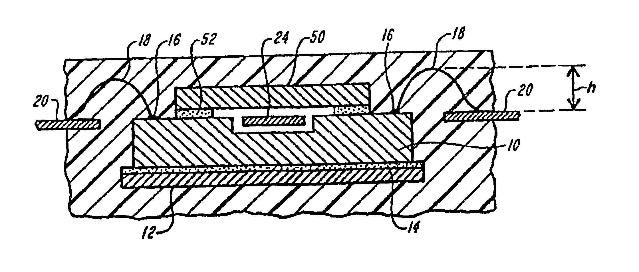
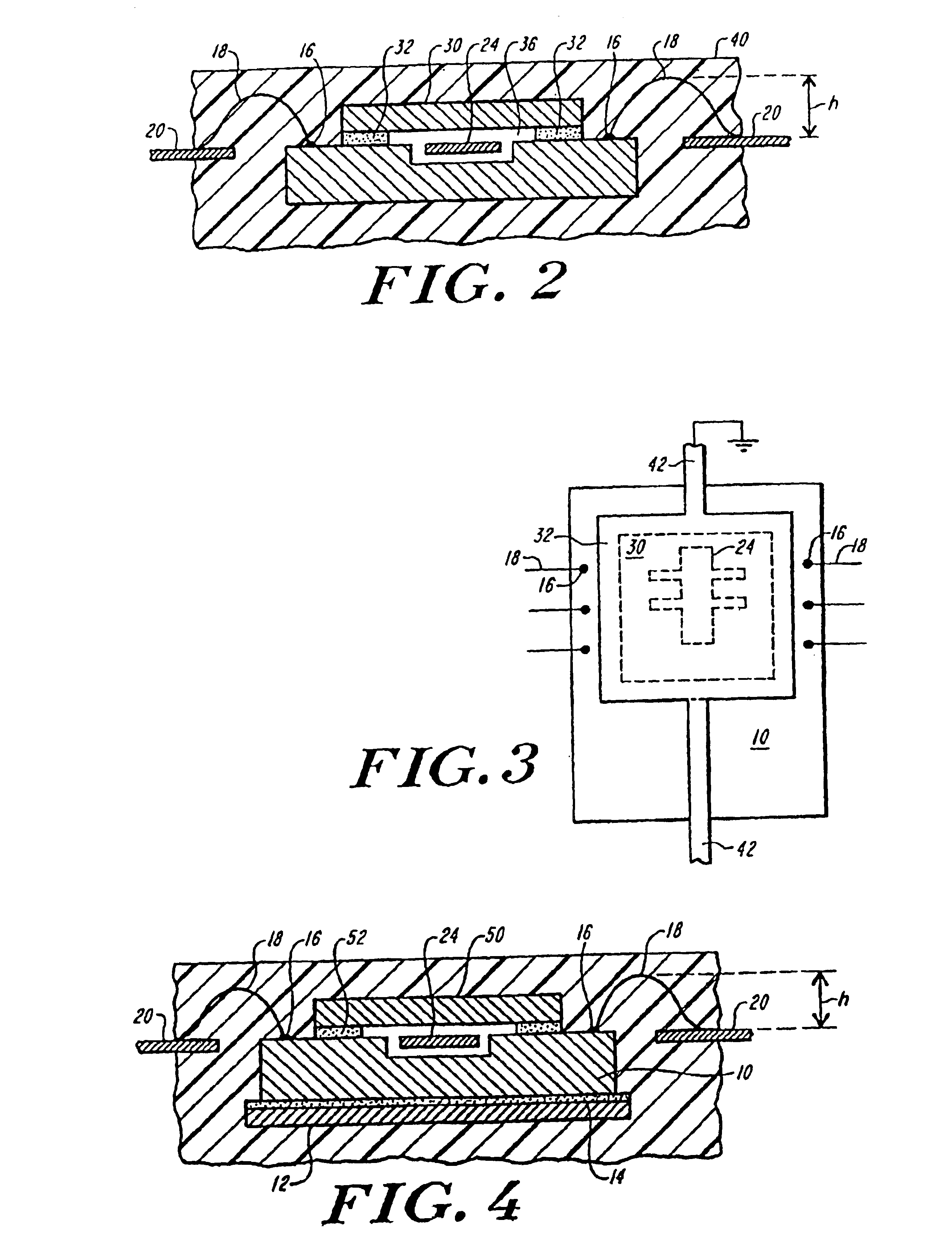
[0022]Referring to FIG. 2, in the present invention, a paddle 30 is bonded over a face of chip 10 with an adhesive layer 32. Paddle 30 replaces the larger paddle 12 as shown in FIG. 1. Referring also to FIG. 3, paddle 30 has a perimeter that fully surrounds mass 24, but preferably does not block access to ballbonds 16. Typically, the area of paddle 30 is less than the area of the die.

[0023]Adhesive layer 32, in addition to bonding paddle 30 to chip 10, serves as a standoff to the die, thus defining between paddle 30 and mass 24 a void region 36 that prevents paddle 30 from contacting mass 24. A cutout region can be formed in the paddle, e.g., with chemical etching or stamping, to help create a larger void region. Preferably, the paddle is made of metal.

[0024]Preferably, the adhesive is organic, which tends to create less mechanical stress than an inorganic adhesive. An example of a thermoset, organic, non-conductive adhesive that can be used is Ablestik 660, available from Ablestik ...

third embodiment

[0034]Referring to FIGS. 6 and 7, in the present invention, a die 60 has a portion 62 to be protected, such as a sensor, formed in a face 64 of the die. Die 60 has a silicon substrate 70 and other various layers (not shown) with a top passivation layer 72, such as glass. A layer 74 of glass or metal is provided over top passivation layer 72 so that it surrounds portion 62. While this layer can include a number of different types of glasses or metals, it is preferred that this layer include a layer 76 of aluminum with an intermediate layer 78 to assist in bonding aluminum layer 76 to passivation layer 72. Intermediate layer 78 is preferably titanium tungsten.

[0035]A cap 80 has a silicon body 82 with a perimeter 88 that is coated with a layer 84 of glass or metal. While a number of different glasses and metals can be used, layer 84 is preferably made of gold. To form the hermetic seal, the cap is provided over the die and is heated to an appropriate temperature, preferably at least ab...


PUM


Abstract

A die has a part that is sealed with a cap. The seal can be hermetic or non-hermetic. If hermetic, a layer of glass or metal is formed in the surface of the die, and the cap has a layer of glass or metal at a peripheral area so that, when heated, the layers form a hermetic seal. A non-hermetic seal can be formed by bonding a cap with a patterned adhesive. The cap, which can be silicon or can be a metal paddle, is electrically coupled to a fixed voltage to shield the part of the die.

Description

CROSS REFERENCED TO RELATED APPLICATION[0001]This continuation of U.S. application Ser. No. 09 / 947,859, filed Sep. 6, 2001, now U.S. Pat. No. 6,621,158, which is a continuation of U.S. application Ser. No. 08 / 471,748, filed Jun. 6, 1995, now U.S. Pat. No. 6,323,550, the entirety of which is incorporated herein by reference.FIELD OF THE INVENTION[0002]The present invention relates to packaging and sealing an integrated circuit die.BACKGROUND OF THE INVENTION[0003]To package a device in plastic, a typical die having an integrated circuit in a top face is bonded onto a paddle so that the bottom face of the die is bonded to the paddle. The die is then coupled to a leadframe with wirebonds. The die, paddle, and leadframe are encapsulated in plastic by flowing plastic over them at high temperature and pressure. This typical encapsulating process cannot be used with some dies, such as micromachined devices that have movable components, because the flowing plastic would affect the movement ...

Claims


Application Information

Patent Timeline
IPC IPC(8): G01P1/02G01P1/00H01L23/02
CPCB81B7/0051G01P1/023G01P15/125H01L23/49503H01L23/49513B81C1/00269H01L2924/10253H01L23/10H01L2224/32245H01L2224/48091H01L2224/48247H01L2224/48465H01L2224/73265H01L2924/01013H01L2924/01079H01L2924/16235H01L2924/3025G01P2015/0814H01L2924/01019H01L2924/1461H01L2924/07802H01L24/48H01L2924/00014H01L2924/00H01L2924/10157H01L2924/14H01L2924/181H01L2924/00012H01L2224/45099H01L2224/45015H01L2924/207
Inventor MARTIN, JOHN R.ROBERTS, JR., CARL M.
Owner ANALOG DEVICES INC
Why Eureka
Try Eureka