
High frequency filter device and related methods

a filter device and high frequency technology, applied in the field of electronic devices, can solve the problems of affecting the effective performance of certain electrical/electronic equipment, affecting the operation of certain telecommunications, computer and other electrical/electronic equipment, and affecting the operation of certain devices, etc., and achieve the effect of broadening the attenuation frequency band of the filter device and different impedances

Inactive Publication Date: 2005-06-28
LAIRD TECH INC
View PDF25 Cites 16 Cited by
  • Summary
  • Abstract
  • Description
  • Claims
  • Application Information

AI Technical Summary

Benefits of technology

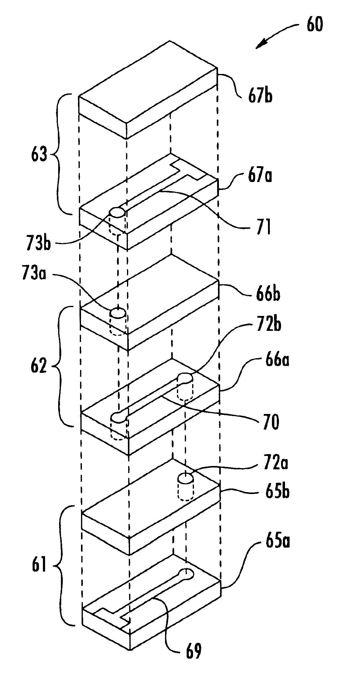
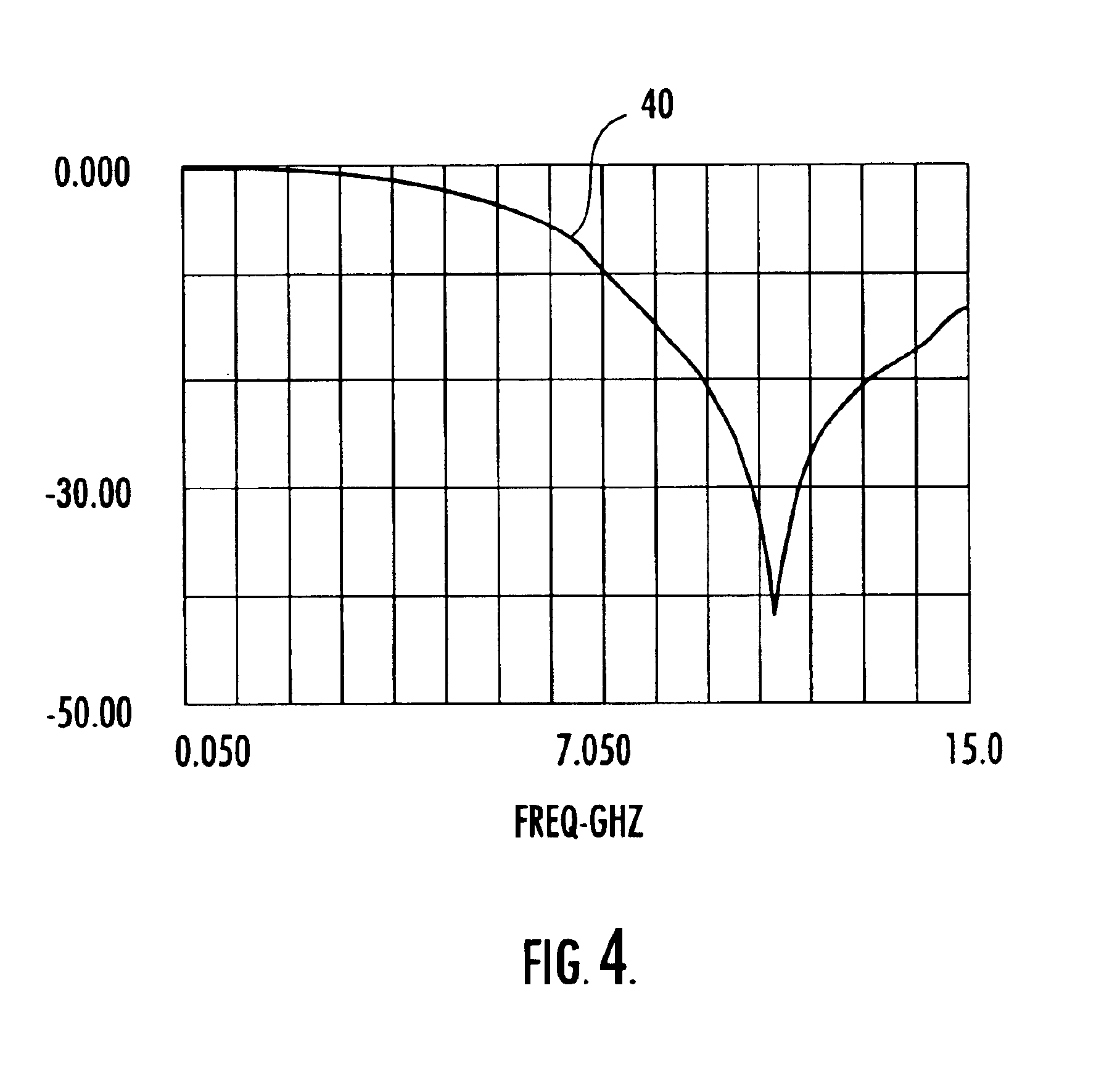
[0009]In particular, the different operating characteristics may be different impedance versus frequency characteristics to thereby broaden an attenuation frequency band of the filter device. For example, at least one of the ferrite layers may include iron deficient zinc ferrite to provide desired impedance characteristics at higher frequencies, and at least one other of the ferrite layers may include copper nickel zinc ferrite to provide desired impedance characteristics at lower frequencies. Specifically, the iron deficient zinc ferrite may include about 30-40 percent by weight ZnO and about 60-70 percent by weight Fe2O3.

Problems solved by technology

Electromagnetic interference (EMI) or radio frequency (RF) interference from electrical devices, signal sources, etc., can interrupt or otherwise degrade the effective performance of certain telecommunication, computer, and other electrical / electronic equipment.
EMI can be a particular problem between about 800 MHz and about 15 GHz, for example.
However, soft ferrites based on a spinel crystal structure are not traditionally used over 1 GHz or so because the ferromagnetic frequency response thereof decays rapidly in this frequency range.
While other types of ferrite are used in microwave frequencies in devices such as monolithic microwave integrated circuits (MMICs) and in elements of radar devices that operate in the low to high GHz frequency range, such devices may not readily lend themselves to relatively small-scale applications.

Method used


Image

  • High frequency filter device and related methods
  • High frequency filter device and related methods
  • High frequency filter device and related methods

Examples


example 1

Iron Deficient Zinc Ferrite Material Made from Raw Materials

1.0 Product Formulation and Mixing Requirements for ZF10 Calcine.

[0038]1.1 Mix the following materials using an Elrich model R-07 (or other suitable mixer):

[0039]

RawMaterialSupplierGradeWeightIronThyssenPremium110.2 ±OxideKruppGround1.0 lbs.StahlThyssenZincZochemZoco 10381.9 ±Oxide0.6 lbs.

[0040]1.2 Pull sample for x-ray on the first two mixes of each lot to ensure proper mixture, consistency, etc. Mixing times are as follows:

[0041]

StepTime / QuantityComment1. Pre-mix on˜1 minutehigh speed:2. Add water:˜3.5 gallonsAdjust as necessaryto achieve pelletintegrity.3. Mix on high˜6 minutesAdjust as necessaryspeed:to achieve pelletintegrity.4. Mix on low˜4 minutesAdjust as necessaryspeed:to achieve pelletintegrity.5. Pan on:As needed toachieve ˜0.1-.02″ pellet

2.0 Drying.

[0042]2.1 Dry in suitable dryers under the following condition:

[0043]

Temp:425° F.Time:24 hours (minimum)

[0044]2.2 Another option is to allow the material to dry next ...

example 2

Iron Deficient Zinc Ferrite Made from Pre-Processed Zinc Ferrite Material

1.0 Lot Make-Up

[0047]ZF-10 Calcine—99%

[0048]Bi2O3—1%

2.0 Mill with Attritor (Model S100)

[0049]2.1 Rinse attritor thoroughly prior to use.

[0050]2.2 Calcine Charge:

[0051]

ZF-10 Calcine Wt.800 lbsBi2O3: 8 lbsWater:33 gallonsColloid 102:1000 ccFoamblast 338 80 cc(RossChem):

[0052]2.3 Up to 4 gallons of water may be added to aid unloading (as pulp density permits). Also, 500 cc of colloid may also be added to each mill to aid in unloading.

[0053]

MillAs necessary to achieve BET targetTime:BET*2.15-2.35 m2 / gTarget:Pulp2450-2500Density:*Critical Parameter

[0054]2.4 Check pH on each attritor mill when the BET target has been achieved, and record results on attritor mill log.

3.0 Slurry Screening.

[0055]3.1 Screen all slurry transferred to the tank(s) with Sweco 30″ or other suitable screener.

[0056]Screen size: 150 MG (with backing wire)

4.0 Slurry Tanks.

[0057]4.1 Clean all slurry tanks thoroughly prior to use. All slurry trans...

example 3

Copper Nickel Zinc Ferrite Material Made from Raw Materials

1.0 Dry Mix Composition (Raw Pellets).

[0082]1.1 Normalize elements below to composition specified.

[0083]

Nominal EXZNFE-235 finalMnO: 0.15 wt. %Fe2O364.91 wt. %NiO 0.11 wt. %CuO 0.02 wt. %ZnO34.81 wt. %Bi2O3 0.00%SiO2 0.00%

2.0 Final Composition Adjustment.

[0084]2.1 Maximum tank adjustment percentage on final composition adjustment: 3.00%.

[0085]2.2 Re-normalize elements below to composition specified.

[0086]

Nominal EXZNFE-235 finalMnO: 0.15 wt. %Fe2O364.91 wt. %NiO 0.11 wt. %CuO 0.02 wt. %ZnO34.81 wt. %Bi2O3 0.00%SiO2 0.00%

3.0 Water Addition.

[0087]3.1 Total adjustment (lb.)×0.04=gallons of water.

4.0 Mill Time.

[0088]4.1 Additions<1.0%=15 minutes.

[0089]4.2 Additions>1.0%=30 minutes.

5.0 BET Measurement (#2 Quantasorb).

[0090]5.1 Calcine Mills: 2.15-2.36 m2 / g (once Coulter reaches 2.80 microns (ferrite)).

6.0 Reference Part Print for Final Product Specifications.

[0091]It will therefore be appreciated that filter devices in accordance...


PUM

PropertyMeasurementUnit
ferromagnetic frequency responseaaaaaaaaaa
frequencyaaaaaaaaaa
frequencyaaaaaaaaaa

Abstract

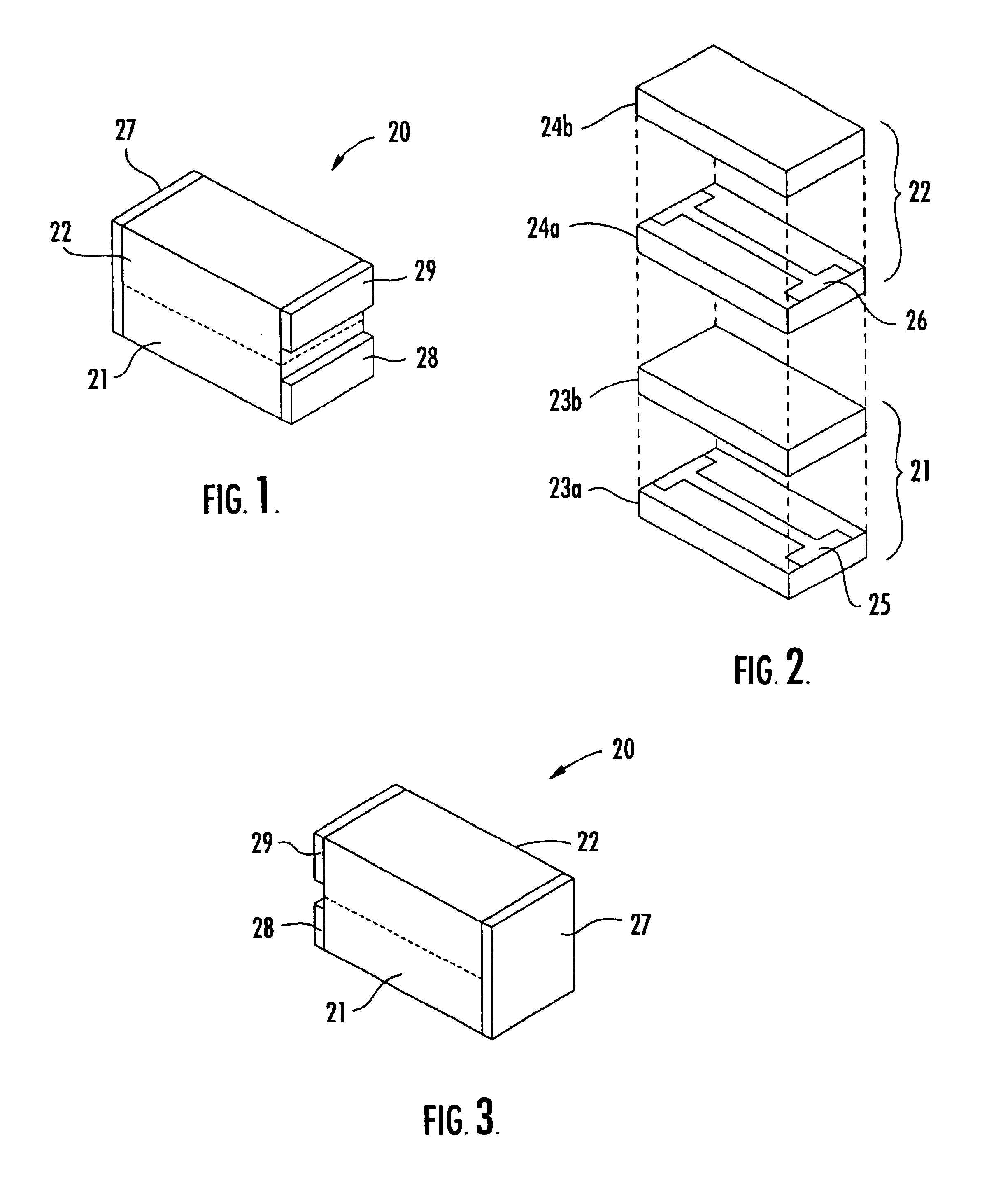
A filter device may include a plurality of ferrite filters laminated together in vertically stacked relation, where each ferrite filter may include a pair of ferrite layers laminated together in vertically stacked relation and a lateral conductor extending therebetween. The filter device may also include at least one vertical conductor connecting the lateral conductors together in series. Moreover, at least some of the ferrite filters may have different operating characteristics. In particular, the different operating characteristics may be different impedance versus frequency characteristics to thereby broaden an attenuation frequency band of the filter device.

Description

CROSS-REFERENCE TO RELATED APPLICATIONS[0001]This application claims the benefit of U.S. Provisional Application No. 60 / 313,639, filed Aug. 20, 2001, which is hereby incorporated herein in its entirety by reference.FIELD OF THE INVENTION[0002]The present invention relates to the field of electronic devices, and, more particularly, to filters for use in electronic circuits and related methods.BACKGROUND OF THE INVENTION[0003]Electromagnetic interference (EMI) or radio frequency (RF) interference from electrical devices, signal sources, etc., can interrupt or otherwise degrade the effective performance of certain telecommunication, computer, and other electrical / electronic equipment. As a result, filters are commonly used in numerous types of electronic circuits to allow signals of a desired frequency to pass along a signal path, for example, while reducing the propagation of other undesired frequencies.[0004]One particular type of filter commonly used in electrical and electronic dev...

Claims


Application Information

Patent Timeline
Patent Type & Authority Patents(United States)
IPC IPC(8): H01P1/215H01P1/20
CPCH01P1/215Y10T29/4902
Inventor BODLEY, LESLEY PAIGESMITHSMITH, MARJORIE E.MEADORS, RICHARD W.PARIS, HENRY G.
Owner LAIRD TECH INC
Learn More